I need help on this Simple circuits problem: Design a simple RLC circuit in series configuration:...
I need help on this Simple circuits problem:
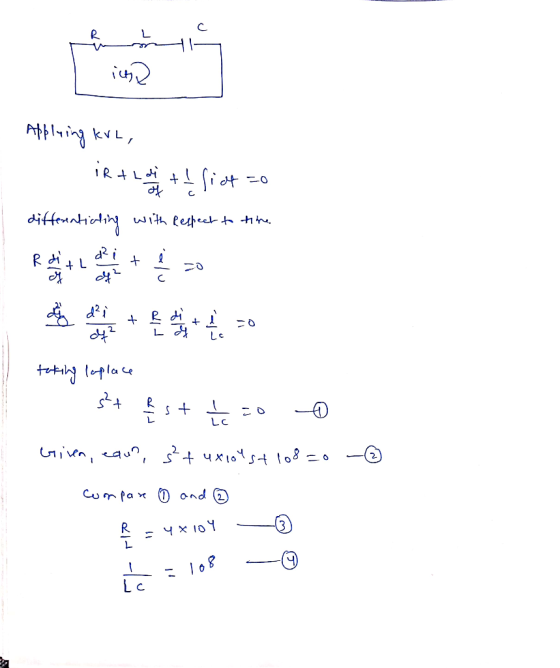
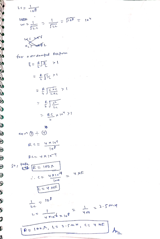
Design a simple RLC circuit in series configuration:
- shows an over-damped response
- satisfies the following characteristic equation:

Work will be helpful such as the analytical solution along with the drawing of the circuit. Thanks & I will rate ASAP.
Homework Answers
Add Answer to:
I need help on this Simple circuits problem:
Design a simple RLC circuit in series configuration:...
1. A paralll RLC circuit consists of a A series RLC circuit consists of the same...
 1. A paralll RLC circuit consists of a A series RLC circuit consists of the same 5000 Ω resistor, 1.25 H inductor, and 8 nF capacitor. a) Find the roots of the characteristic 2. 5000 Ω resistor, a 1.25 H inductor, and an 8 nF capacitor. a) Find the roots of the characteristic equation equation b) Is the response over-damped or b) Is the response over-damped or under-damped? under-damped? c) How would you need to change the resistance to get...
RLC circuit in series A resistor R is connected in series to an inductor L and...
RLC circuit in series A resistor R is connected in series to an inductor L and a capacitor C, without any external emf sources. (a) Using the fact that the energy stored in both the capacitor and the inductor is being dissipated in the resistor, show that the charge on the capacitor q(t) satisfies the differential equation d^2 q/ dt^2 + Rdq/Ldt + q/LC = 0. This is the equation of a damped oscillator and it has a solution of...
Question 5 20 pts Н w R1 L1 C1 A parallel RLC circuit is shown with...
 Question 5 20 pts Н w R1 L1 C1 A parallel RLC circuit is shown with a DC current source I1 = IDc feeding the parallel combination. The circuit is shown with the source II being turned ON at time to Assume the capacitor C1 and inductor L1 are initially unchanged. Denote the currents IR, IL, Io as the currents through RI, L1 and C1 respectively. 7/28/20, 5:12 am https://useonline.southalabama.edu/courses/41 a) Employ KCL to obtain the integro-differential equation for the...
ECE LTSPICE Homework help? 1a) Design, simulate (in LT Spice) a simple first order RLC circuit wh...
ECE LTSPICE Homework help? 1a) Design, simulate (in LT Spice) a simple first order RLC circuit which can be used to display both an underdamped and overdamped natural response.
Please do the hand calculation required for this circuit Circuit-2: Response of RLC Circuit to multiple...
 Please do the hand calculation required for this circuit
Circuit-2: Response of RLC Circuit to multiple power supplies 1. Switches1 and 2 in the circuit below are synchronized. When switch 1 is opened, switch 2 closes, and vice versa. Switch 1 has been open a long time before closing at r-0. Find the expression for i(l) for 120 2. Plot the current i() versus using Matlab Build the circuit in PSpice, plot the current ito versus through simulations and verify...
Please do the hand calculation required for this circuit
Circuit-2: Response of RLC Circuit to multiple power supplies 1. Switches1 and 2 in the circuit below are synchronized. When switch 1 is opened, switch 2 closes, and vice versa. Switch 1 has been open a long time before closing at r-0. Find the expression for i(l) for 120 2. Plot the current i() versus using Matlab Build the circuit in PSpice, plot the current ito versus through simulations and verify...
pleasse some one help me with theseeee questions -8. Design an RLC circuit that is a...
 pleasse some one help me with theseeee questions
-8. Design an RLC circuit that is a bandpass filter having peak frequency = 1 MHz and band- width = 10 kHz. -9. Design an RLC circuit whose frequency response is the complement of the BPF in Problem - 8-8.
pleasse some one help me with theseeee questions
-8. Design an RLC circuit that is a bandpass filter having peak frequency = 1 MHz and band- width = 10 kHz. -9. Design an RLC circuit whose frequency response is the complement of the BPF in Problem - 8-8.
Function Generatr Inductor Model Ra R, Figure 1 Series RLC Circuit Preliminary This laboratory wi...
 Function Generatr Inductor Model Ra R, Figure 1 Series RLC Circuit Preliminary This laboratory will demonstrate how varying resistance changes the natural response of a series RLC circuit (Fig. 1). The function generator is modeled as an ideal voltage source v(t) 5 u() V in series with source resistance Rs-50Q. After measurements using an LCR meter, the inductor is modeled as an ideal L 90 mH inductor in series with resistance RL-20Q. The capacitance is C-0.22 μF. 1) Calculate the...
Solve all the problems shown below Problem 1 In a source free RLC series circuit If...
 Solve all the problems shown below Problem 1 In a source free RLC series circuit If R=1092 ,L=5H ,and C= 2 mF 1) Find a.,0, and the characteristics roots $,$2. 2) Find the response i(t) knowing that v(0)=5V and i(0)=1A Problem 2 In a source free RLC parallel circuit If R=52 ,L= 1H ,and C= 10 m 1) Find a ,0, and the characteristics roots S1,S2. 2) Find the response V(t) knowing that v(O)=10V and i(0)=5A Problem 3 In a...
The current, i, in a series RLC circuit when the switch is closed at t 0 can be determined from t...
 use MATLAB functions to solve this problem
The current, i, in a series RLC circuit when the switch is closed at t 0 can be determined from the solution of the V 2nd-order ODE to v t-0 d2i ndi 1 where R, L, and c are the resistance of the resistor, the inductance of the inductor, and the capacitance of the capacitor, respectively. (a) Solve the equation for i in terms of L, R, C, and t, assuming that at...
use MATLAB functions to solve this problem
The current, i, in a series RLC circuit when the switch is closed at t 0 can be determined from the solution of the V 2nd-order ODE to v t-0 d2i ndi 1 where R, L, and c are the resistance of the resistor, the inductance of the inductor, and the capacitance of the capacitor, respectively. (a) Solve the equation for i in terms of L, R, C, and t, assuming that at...
 1. A paralll RLC circuit consists of a A series RLC circuit consists of the same 5000 Ω resistor, 1.25 H inductor, and 8 nF capacitor. a) Find the roots of the characteristic 2. 5000 Ω resistor, a 1.25 H inductor, and an 8 nF capacitor. a) Find the roots of the characteristic equation equation b) Is the response over-damped or b) Is the response over-damped or under-damped? under-damped? c) How would you need to change the resistance to get...
 Question 5 20 pts Н w R1 L1 C1 A parallel RLC circuit is shown with a DC current source I1 = IDc feeding the parallel combination. The circuit is shown with the source II being turned ON at time to Assume the capacitor C1 and inductor L1 are initially unchanged. Denote the currents IR, IL, Io as the currents through RI, L1 and C1 respectively. 7/28/20, 5:12 am https://useonline.southalabama.edu/courses/41 a) Employ KCL to obtain the integro-differential equation for the...
 Question 5 20 pts Н w R1 L1 C1 A parallel RLC circuit is shown with a DC current source I1 = IDc feeding the parallel combination. The circuit is shown with the source II being turned ON at time to Assume the capacitor C1 and inductor L1 are initially unchanged. Denote the currents IR, IL, Io as the currents through RI, L1 and C1 respectively. 7/28/20, 5:12 am https://useonline.southalabama.edu/courses/41 a) Employ KCL to obtain the integro-differential equation for the...
 Please do the hand calculation required for this circuit
Circuit-2: Response of RLC Circuit to multiple power supplies 1. Switches1 and 2 in the circuit below are synchronized. When switch 1 is opened, switch 2 closes, and vice versa. Switch 1 has been open a long time before closing at r-0. Find the expression for i(l) for 120 2. Plot the current i() versus using Matlab Build the circuit in PSpice, plot the current ito versus through simulations and verify...
Please do the hand calculation required for this circuit
Circuit-2: Response of RLC Circuit to multiple power supplies 1. Switches1 and 2 in the circuit below are synchronized. When switch 1 is opened, switch 2 closes, and vice versa. Switch 1 has been open a long time before closing at r-0. Find the expression for i(l) for 120 2. Plot the current i() versus using Matlab Build the circuit in PSpice, plot the current ito versus through simulations and verify...
 pleasse some one help me with theseeee questions
-8. Design an RLC circuit that is a bandpass filter having peak frequency = 1 MHz and band- width = 10 kHz. -9. Design an RLC circuit whose frequency response is the complement of the BPF in Problem - 8-8.
pleasse some one help me with theseeee questions
-8. Design an RLC circuit that is a bandpass filter having peak frequency = 1 MHz and band- width = 10 kHz. -9. Design an RLC circuit whose frequency response is the complement of the BPF in Problem - 8-8.
 Function Generatr Inductor Model Ra R, Figure 1 Series RLC Circuit Preliminary This laboratory will demonstrate how varying resistance changes the natural response of a series RLC circuit (Fig. 1). The function generator is modeled as an ideal voltage source v(t) 5 u() V in series with source resistance Rs-50Q. After measurements using an LCR meter, the inductor is modeled as an ideal L 90 mH inductor in series with resistance RL-20Q. The capacitance is C-0.22 μF. 1) Calculate the...
 Solve all the problems shown below Problem 1 In a source free RLC series circuit If R=1092 ,L=5H ,and C= 2 mF 1) Find a.,0, and the characteristics roots $,$2. 2) Find the response i(t) knowing that v(0)=5V and i(0)=1A Problem 2 In a source free RLC parallel circuit If R=52 ,L= 1H ,and C= 10 m 1) Find a ,0, and the characteristics roots S1,S2. 2) Find the response V(t) knowing that v(O)=10V and i(0)=5A Problem 3 In a...
 use MATLAB functions to solve this problem
The current, i, in a series RLC circuit when the switch is closed at t 0 can be determined from the solution of the V 2nd-order ODE to v t-0 d2i ndi 1 where R, L, and c are the resistance of the resistor, the inductance of the inductor, and the capacitance of the capacitor, respectively. (a) Solve the equation for i in terms of L, R, C, and t, assuming that at...
use MATLAB functions to solve this problem
The current, i, in a series RLC circuit when the switch is closed at t 0 can be determined from the solution of the V 2nd-order ODE to v t-0 d2i ndi 1 where R, L, and c are the resistance of the resistor, the inductance of the inductor, and the capacitance of the capacitor, respectively. (a) Solve the equation for i in terms of L, R, C, and t, assuming that at...
Most questions answered within 3 hours.
-
A customer has requested that Lewelling Corporation fill a
special order for 2,400 units of product...
asked 9 minutes ago -
What are two strengths and two weaknesses of hardware,
software, and/or data?
How can the weaknesses...
asked 11 minutes ago -
A and B face the choice of working in a safe
mine at €200/wk or an...
asked 31 minutes ago -
True or false: couldnt figure out these few
- When charges are only located OUTSIDE an...
asked 40 minutes ago -
Given the following function:
int fun1(int count){
int Num ;
for (i = 0; i <...
asked 40 minutes ago -
Please submit your paper topic so that I can review it and make
any necessary suggestions...
asked 41 minutes ago -
Why are there so many theories of addiction? (Consider the
adequacy of each theory in relation...
asked 44 minutes ago -
22mL of 0.1020M Naoh is used in a titration against an unknown
1M acid (30mL). Determine...
asked 53 minutes ago -
Solve for distance using 90 db = 85 db + 20 log (20 ft/
distance)
1.8...
asked 55 minutes ago -
Aluminum is cast in an insulating ceramic mold with no
superheat. The thickness of the casting...
asked 1 hour ago -
Discuss the current status of Ulmus americana and the reasons for
it status. (answer in detail...
asked 1 hour ago -
Q3. A car moves with a constant velocity of 25m/s east with
respect to a person...
asked 1 hour ago