
Homework Answers
Add Answer to:
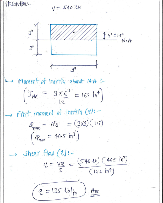
Problem 2: What is the shear flow along the connected surface of the beam below? The...
Beam Cross Sections Shear Force andQ below shows the cross section of an I-beam. The internal...
 Beam Cross Sections Shear Force andQ below shows the cross section of an I-beam. The internal shear force, V, is shown. The figurehb Points B and D are located on the flange. Rank these situations, from greatest to least, on the basis of the value of Q. 3" 1" 1" 1" Least Greatest 123 Or, the value of Q is the same at every point. Please carefully explain your reasoning. Beam Cross Sections Shear Flow I The figure below shows...
Plot the shear force diagram along the length of the beam A cantilever beam as shown...
 Plot the shear force diagram along the length of the beam
A cantilever beam as shown in the figure below is used to support a tip load of 1 kN and an axial compressive load of 10 kN. The beam has a length L 1 m and a square cross-section with side length of 0.05m. [15 marks] 1 kN 1 m
Plot the shear force diagram along the length of the beam
A cantilever beam as shown in the figure below is used to support a tip load of 1 kN and an axial compressive load of 10 kN. The beam has a length L 1 m and a square cross-section with side length of 0.05m. [15 marks] 1 kN 1 m
11 Section 4, Problem 11. A beam is loaded by a shear force V. The beam...
 11 Section 4, Problem 11. A beam is loaded by a shear force V. The beam cross-section is shown below. The moment of inertia of the cross-section is 3471 in 4. The centroid of the cross-section is 6.25 inches from the base. Determine: a) the shear stress at point b) the shear stress at point B. c) the maximum shear stress in the cross-section. X 02:46:51 V = 55 (kips) The maximum shear stress at point A is The maximum...
A beam has a cross section as shown. If the shear force is 12 kip a)...
 A beam has a cross section as shown. If the shear force is 12
kip
a) Calculate the shear stress at 1 in intervals along the
depth of the section
b) Plot the shear stress distribution
4 in. 6 in. 2 in. + -4 in.
A beam has a cross section as shown. If the shear force is 12
kip
a) Calculate the shear stress at 1 in intervals along the
depth of the section
b) Plot the shear stress distribution
4 in. 6 in. 2 in. + -4 in.
4. SHEAR AND MOMENT DIAGRAMS Determine the shear and moment diagrams for the beam shown below....
 4. SHEAR AND MOMENT DIAGRAMS Determine the shear and moment diagrams for the beam shown below. There is a pin at A and a rocker at B. a. There are 3 sections. Draw the FBD for each section. Also, give the shear and moment equation for each section. 125 lb/ft 1000 lb х 10 ft 6 ft 10 ft
For the beam shown in the figure below a. Draw the shear and moment diagrams for this beam
 For the beam shown in the figure below a. Draw the shear and moment diagrams for this beam b. Calculate the maximum bending stress, maximum axial stress, and maximum shear stress acting on the beam cross section c. Sketch the distributions of shear stresses and bending stresses acting on the beam cross section at the locations where these stresses are maximum.
Design for Shear Dus Tuosday April 23, 2019 Problem # 1: For the beam shown below, design the cri...
 Design for Shear Dus Tuosday April 23, 2019 Problem # 1: For the beam shown below, design the critical section for shear usng # 10 U-shaped strups. Neglect cokumn width n your cakcuhtion Given: b-350 mm,f,' 21 MPa.,6-420 MPa, and d-600 + 35-635 mm. 00 KN (L) 40 KN/m (D 600 mm 740 mm 8 #29 70 mm 4 m 4 m 70 mm 350 mm Problem # 2: Re-solve Example (3) in te lecture notes (Notes l 1) using...
4. SHEAR AND MOMENT DIAGRAMS Determine the shear and moment diagrams for the beam shown below....
 4. SHEAR AND MOMENT DIAGRAMS Determine the shear and moment diagrams for the beam shown below. There is a pin at A and a rocker at B. a. There are 3 sections. Draw the FBD for each section. Also, give the shear and moment equation for each section. у 125 lb/ft 1000 lb х A 10 ft B 6 ft 10 ft
4. SHEAR AND MOMENT DIAGRAMS Determine the shear and moment diagrams for the beam shown below....
 4. SHEAR AND MOMENT DIAGRAMS Determine the shear and moment diagrams for the beam shown below. There is a pin at A and a rocker at B. a. There are 3 sections. Draw the FBD for each section. Also, give the shear and moment equation for each section. у 125 lb/ft 1000 lb Х A B 10 ft 6 ft 10 ft
4. SHEAR AND MOMENT DIAGRAMS Determine the shear and moment diagrams for the beam shown below....
 4. SHEAR AND MOMENT DIAGRAMS Determine the shear and moment diagrams for the beam shown below. There is a pin at A and a rocker at B. a. There are 3 sections. Draw the FBD for each section. Also, give the shear and moment equation for each section. у 125 lb/ft 1000 lb 10 ft 6 ft 10 ft B
 Beam Cross Sections Shear Force andQ below shows the cross section of an I-beam. The internal shear force, V, is shown. The figurehb Points B and D are located on the flange. Rank these situations, from greatest to least, on the basis of the value of Q. 3" 1" 1" 1" Least Greatest 123 Or, the value of Q is the same at every point. Please carefully explain your reasoning. Beam Cross Sections Shear Flow I The figure below shows...
 Plot the shear force diagram along the length of the beam
A cantilever beam as shown in the figure below is used to support a tip load of 1 kN and an axial compressive load of 10 kN. The beam has a length L 1 m and a square cross-section with side length of 0.05m. [15 marks] 1 kN 1 m
Plot the shear force diagram along the length of the beam
A cantilever beam as shown in the figure below is used to support a tip load of 1 kN and an axial compressive load of 10 kN. The beam has a length L 1 m and a square cross-section with side length of 0.05m. [15 marks] 1 kN 1 m
 11 Section 4, Problem 11. A beam is loaded by a shear force V. The beam cross-section is shown below. The moment of inertia of the cross-section is 3471 in 4. The centroid of the cross-section is 6.25 inches from the base. Determine: a) the shear stress at point b) the shear stress at point B. c) the maximum shear stress in the cross-section. X 02:46:51 V = 55 (kips) The maximum shear stress at point A is The maximum...
 A beam has a cross section as shown. If the shear force is 12
kip
a) Calculate the shear stress at 1 in intervals along the
depth of the section
b) Plot the shear stress distribution
4 in. 6 in. 2 in. + -4 in.
A beam has a cross section as shown. If the shear force is 12
kip
a) Calculate the shear stress at 1 in intervals along the
depth of the section
b) Plot the shear stress distribution
4 in. 6 in. 2 in. + -4 in.
 4. SHEAR AND MOMENT DIAGRAMS Determine the shear and moment diagrams for the beam shown below. There is a pin at A and a rocker at B. a. There are 3 sections. Draw the FBD for each section. Also, give the shear and moment equation for each section. 125 lb/ft 1000 lb х 10 ft 6 ft 10 ft
 Design for Shear Dus Tuosday April 23, 2019 Problem # 1: For the beam shown below, design the critical section for shear usng # 10 U-shaped strups. Neglect cokumn width n your cakcuhtion Given: b-350 mm,f,' 21 MPa.,6-420 MPa, and d-600 + 35-635 mm. 00 KN (L) 40 KN/m (D 600 mm 740 mm 8 #29 70 mm 4 m 4 m 70 mm 350 mm Problem # 2: Re-solve Example (3) in te lecture notes (Notes l 1) using...
 4. SHEAR AND MOMENT DIAGRAMS Determine the shear and moment diagrams for the beam shown below. There is a pin at A and a rocker at B. a. There are 3 sections. Draw the FBD for each section. Also, give the shear and moment equation for each section. у 125 lb/ft 1000 lb х A 10 ft B 6 ft 10 ft
 4. SHEAR AND MOMENT DIAGRAMS Determine the shear and moment diagrams for the beam shown below. There is a pin at A and a rocker at B. a. There are 3 sections. Draw the FBD for each section. Also, give the shear and moment equation for each section. у 125 lb/ft 1000 lb Х A B 10 ft 6 ft 10 ft
 4. SHEAR AND MOMENT DIAGRAMS Determine the shear and moment diagrams for the beam shown below. There is a pin at A and a rocker at B. a. There are 3 sections. Draw the FBD for each section. Also, give the shear and moment equation for each section. у 125 lb/ft 1000 lb 10 ft 6 ft 10 ft B
Most questions answered within 3 hours.
-
What is the standard error of M (denoted as
σM ) ?
Options:
The mean of...
asked 21 minutes ago -
Explain the role of n, the sample size, in determining the size
of a generated confidence...
asked 10 minutes ago -
Kelsey Drums, Inc., is a well-established supplier of fine
percussion instruments to orchestras all over the...
asked 24 minutes ago -
In a criminal case, the state must not prove its case beyond a
reasonable doubt. T/F
asked 29 minutes ago -
5.6 dm^3 of gaseous HCl (as measured in normal conditions) is
dissolved in 100 cm^3 of...
asked 38 minutes ago -
The hammer throw is a track-and-field event in which a 7.2-kg
ball (the ''hammer''), starting from...
asked 55 minutes ago -
Evaluate a specific listening situation using the Sapir-Whorf
and Bernstein hypothesis. What was thecontext? What was...
asked 1 hour ago -
Recall that if X is a Student’s t random variable with n df,
then by definition...
asked 1 hour ago -
A charge of -2.95 µC is fixed in place. From a horizontal
distance of 0.0470 m,...
asked 1 hour ago -
Consider the following information:
Your company makes widgets. You are trying to figure out what
volume...
asked 1 hour ago -
Math 333 Plz help ASAP
The yield of a chemical process is being studied. From previous...
asked 1 hour ago -
Cobb-Douglas Preferences: Cobb-Douglas preferences on the
consump-
tion set R2+ can be represented by a utility...
asked 1 hour ago