Question


necessity of cutting holes in m on the construction ste 12.11. 12.15). Thack etions a sed for top and bottom plates, e construction, shemperature that col tural shapes. Prers arejoist n uctions and furring chae To manufachh sel is fed from dwork the etaoucingabrs can nest into them. e slightly oversized so that tud Chapter 11) and fold it into efficient for lighter bracing and fran ing tasks. Other, more shapes are also available. framing. The term "light gauge" refers t (gauge) of the steel sheet from which the members are made the relative thinness The strength and stiffness of member depend on its shape thickness of sheet metal used as well as the strength and in its sire. and out in the same manner as a THE CONCEPT OF LIGHT GAUGE STEEL CONSTRUCTION The steel used in light gange manufacture. The range of standard A1003 and is metallic-coated bearing and nonbearing men Light gauge steel construction is the with zinc or aluminum-zinc alloy to are listed in Figure 12.2. Steel i light frame construction. The exter ness of the metallic coating can be 50,000 psi (230 or 350 MPa) is nal dimensions of the standard sizes varied, depending on the severity of of light gauge members correspond the environment in which the mem identified using a standard closelh to the dimensions of the stan- bers will be placed noncombustible equinalent of wood protect against corrosion. The thick-yield strengths of both 33,000 Light gauge steel members clature, similar to that used with h dard sizes of nominal 2-inch (38mm) For wall, floor, and roof fram- rolled steel structural shapes For framing lumber. These steel members ing the steel is formed into shador e ample, a fiks lG24ǐ mr nler studs, joists, and rafters in much the ure 12.1). The webs of these mem section S"), 1.625 inch wide (16 are used in framing as clo ey spaced 쎄stans also called Csm tons (Fig. 60Anch-deep (ton dorpest same way as wood light frame mem- bers may be punched at the factory made from 54-mil-thick sheet metal bers are used, and a light gaage steel to provide holes at 2-foot (600-mm) 54"). Standard designations and the frame building may be sheathed, intervals; these allow wiring. piping. range of sizes available for common insulated, wired, and finished inside and bracing to pass through without member types are listed in Figure 123, FIGURE 12. Three typical light gauge steel framing member shapes, from left to right: studs or joists, channels, and tracks.
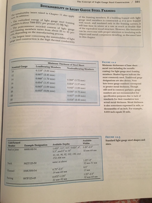
The Concept of Light Gauge Steel Construction /501 SUSTAINABILITY IN LIGHT GAUGE STEEL FRAMING sustainability issues raised in The l about 7000 BTU per pound (15 MJ/kg) The postconsumer i depending on the manufacturing process. Chapter 11 also apply here. In addition: ert. odied energy of light gauge steel framing Wah of the framing members. If a building framed with light gauge steel members is constructed as if it were framed with wood, and insulated only in the framing cavities, it will lose heat in winter at a rate as much as double that of the equivalent wood structure. However, this limitation can be overcome with proper attention to insulating tech niques and metal component detailing, as discussed later in this chapter recycled conten ins members varies from about 25 to 45 per niques and metal compon t of light gauge t issue concerning the sustainability of light Th tel construction is the high thermal conductivity FIGURE 12-2 Minimum thicknesses of base sheet Minimum Thickness of Steel Sheet Nominal Gauge 10 Nonloadbearing Membersmetal (not including the metallic 0.118 (3.00 mm) 0.097" (2.45 mm) 0.068" (1.72 mm) 0.054 (1.37 mm) 0.043 (1.09 mm) 0.033" (0.84 mm) coating) for light gauge steel framing members. Shaded igures indicate the most commonly used. Traditional gouge designations are also shown. Note how lower to greater metal thickness. Though still used in commson parlance, gauge numbers are not recommended for specification purposes due to lack of standards for their translation into actual metal thickness. Metal thickness is also sometimes expressed in mils, or thousandths of an inch. For example, 0.033 inch equals 33 mils. 14 16 0.068 (1.72 mm) 0054 (1.37 mm) 0.043 (1.09 mm) 0.030 (0.75 mm) 0.027 (0.68 mm) 0.018 (0.45mm) gauge numbers 25 FIGURE 12.3 Standard light gauge steel shapes and Cold-Formed Member Available Depths Example Designation 00S16254 625,2.5,3.5,3.625,4. 1.25-2.5 5.5, and 6 to 16 41, 64, 90, 92, 102, 140, and 152-406 same as above Send on Jois 32 mN-64 Track Channel250U050-54 Furring087F12543 1.2-2 32m-51 0.5 13 M 1.25-25 32-64 862T125-30 0.75-2.5 19 MN-64m 0.875-1.25 22M-32m
502Chapter 12 Light Gauge Stel Frame Construrtion ateel framing. End clips are joim memsbers that meett the foundation. Joist hangesd joists to beaders and trim openings The web stiffener assembly tchat is inserted a joist and screwed to its veriid eo help transmit wall loads w.. through the joist. The remain accessories are used for V BRACING FLAT STRAP BRACING held electric or pneumatic tools, thee screws are plated with cadmium rinc to resist corrosion, and they are available in an assortment of dan COLD ROLLED CHANNEL eters and lengths to suit a full rane OIST NANGER of connection needs. Welding is ohes employed to assemble panels of lige gauge steel framing that are prefab ricated in a factory, and is sometime used on the building site where stop ger connections are needed.Other manufacturers produce in the joining and bracing of mem lening techniques include hand-heil clinching devices that join memhens without screws or welds and pacunu cally driven pins that penetraie te proprietary. improved member bers (Figure 12.4) types. For example, the cross-secLike wood light members, light tional profile of a stud or joist may gauge steel shapes are furnished in be altered to enhance its strength standard lengths. They are cut to and stiffness. Or, studs may be length on the construction job site, passed through steel rollers that with power saws, or special electric produce a dense array of dimples or hand shears, depending on their LIGHT GAUGE STEEL in the formed metal. The addi- thickness. For large projects, mem FRAMING tional cold working of the metal bers may be delivered precut to the that occurs during this process and required lengths. the finished patterning of the sur Light gauge steel members face produce a stud with greater usually joined with sdl/drilling sonus, gauge steel members is analoge strength and stiffness. In addition, a which drill their own holes and form to that described in Chapter are a building constructed he sequence of construction f with lig wide variety of angles, straps, plates, helical threads in the holes as they wood light framing (Figure channels, and other shapes are used are installed. Driven rapidly by hand through 12.12). Framing pr
Light Gauge Steel Framing /503 Steel joist rood rafter End cip Aschor clip Steel joust root rater Steel joist sohi tranming R DAVE A RIDGE neated steel joists FIGURE 12-5 Typical light gauge framing details Each detail is keyed by letter to a circle on the central whole-building diagram included as part of this figure, to show its location in the frame. (A) A pair of nested joists makes a boxlike ridge bram.(B) Anchor clips are sandwiched between the ceilling joists and rafters to hold the roof framing down to the wall. (C) A web stiffener helps transmit vertical forces from each stud through the end of the joist to the stud in the Boor below. Mastic adhesive cushions the joint between the sublloor and the steel framing. D Foundation clips anchor the entire Erame to the foundation. (E) At interior joist bearings, joists are overlapped back to back and a web stiffener is inserted channel Crunner- C JOIST BEARING AT UPPER FLOOR boagh plywood Web stiffener anto closure Pnwood subdoor Neb stitener Grout and shinm Sheel joists s requined Poundation clip Steel stud or beam E. INTERYOR JOIST BEARING D JOIST BEARING AT FOUNDATIoN
504/Chapter 12 . Lighe Gauge Steel Frame Constraction Celing jou N. GABLE END FRAMING Closure channel or joilst section End tabs- GJOIST PARALLEL TO END WALL Closure channel or joist section DETAIL KEY FIGURE 12.5 comtinued (E G) Short crosspieces brace the last joist at the end of the building and help transmit stud forces through to the wall below. (h) Like all these details, the gable end framing is directly analogous to the corresponding detail for a wood light frame building as shown in Chapter 5. E joIST PARALLEL TO FOUNDATION Exercise
Light Gauge Steel Framing /505 Opening FIGURE 12.6 Headers and trimmers for floor opening are doubled and nested to create strong, stable bos member. Ouly ooe Joist hanger Double joist header (nested) vertical flange of the joist hanger is attached to the joist; the other flange Steel joist framing would be used instead if the web of the into header joist were oriensed to the left rather than the right. Double joist trimmer (nested) FIGURE 12.7 A typical window or door head detail. The header is made of two joists placed with their open sides together. The top plate of the wall, which is a runner channel, continues over the top of the beader. Another runner channel is cut and folded at each end to frame the top of the opening. Short studs are inserted between this chaneel and the header to maintain the rhrythm of the stads in the wall. Runper channel Steel stud
Homework Answers

Know the answer?
Add Answer to:
Auge Steel Framing Details 1. Complete all light g auge steel componente ir the following wall se...
Not the answer you're looking for?
Ask your own homework help question.
Our experts will answer your question WITHIN MINUTES for Free.
Similar Homework Help Questions
summatize the following info and break them into differeng key points. write them in yojr own...
 summatize the following info and break them into differeng key points. write them in yojr own words
apartus
6.1 Introduction—The design of a successful hot box appa- ratus is influenced by many factors. Before beginning the design of an apparatus meeting this standard, the designer shall review the discussion on the limitations and accuracy, Section 13, discussions of the energy flows in a hot box, Annex A2, the metering box wall loss flow, Annex A3, and flanking loss, Annex...
summatize the following info and break them into differeng key points. write them in yojr own words
apartus
6.1 Introduction—The design of a successful hot box appa- ratus is influenced by many factors. Before beginning the design of an apparatus meeting this standard, the designer shall review the discussion on the limitations and accuracy, Section 13, discussions of the energy flows in a hot box, Annex A2, the metering box wall loss flow, Annex A3, and flanking loss, Annex...
ADVERTISEMENT
Need Online Homework Help?
Ask
a QuestionGet Answers For Free
Most questions answered within 3 hours.
Most questions answered within 3 hours.
ADVERTISEMENT
ADVERTISEMENT
Active Questions
-
What features are centralized in your web application by master
pages? How are master pages implemented...
asked 16 seconds ago -
In your opinion, which provides the most benefit to an
organization, a budget or the budgeting...
asked 3 minutes ago -
Write the expression for the molecular wavefunction of (i) a
s-pz sigma bond and (ii) a...
asked 7 minutes ago -
It costs Crane Company $28 of variable costs and $10.00 of
allocated fixed costs to produce...
asked 22 minutes ago -
Explain the following basis of electron configuration i) the
electron affinity of S is +200kJ mol-1
asked 31 minutes ago -
Determine the pH of a 0.10 M
CH3NH3Cl solution.
(Kb
(CH3NH2) = 4.4 x 10⁻⁴)
2.18...
asked 40 minutes ago -
Asolid metal sphere with radius 0.470 m carries a net charge of
0.200 nC .
Part...
asked 35 minutes ago -
Determine the pH of a 0.0500 M KBr solution (using activity
coefficients when needed)
( please...
asked 37 minutes ago -
Bender's skateboards have the following manufacturing
expenses:
Direct Materials: $10/unit
Direct Labor: $8/unit
Rent: $10,000/month
Depreciation:...
asked 46 minutes ago -
9) A resistor is connected to a capacitor of 4 micro-farads
without a battery. The initial...
asked 54 minutes ago -
Via Gelato is a popular neighborhood gelato shop. The company
has provided the following cost formulas...
asked 1 hour ago -
The Williams have a stock they have held for over a year that
they believe is...
asked 2 hours ago
ADVERTISEMENT