
Homework Answers
Add Answer to:
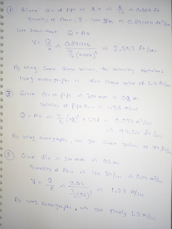
Urban Development II CA 2321 1. Calculate the velocity of flow in an 8 inch diameter pipe when th...
A 1.10 inch diameter pipe is required to carry 47.5 gpm. What flow velocity is required...
A 1.10 inch diameter pipe is required to carry 47.5 gpm. What flow velocity is required in ft/s?
A 2.55 inch diameter pipe is required to carry 46.1 gpm. What flow velocity is required, in ft/s?
A 2.55 inch diameter pipe is required to carry 46.1 gpm. What flow velocity is required, in ft/s?
A 1.40 inch diameter pipe is required to carry 37.9 gpm. What flow velocity is required,...
A 1.40 inch diameter pipe is required to carry 37.9 gpm. What flow velocity is required, in ft/s? The answer should be 7.90 ft/s. I'm lost how to get it.
Sulphuric acid is flowing through a 2.5 inch diameter and 50ft long pipe with a velocity...
Sulphuric acid is flowing through a 2.5 inch diameter and 50ft long pipe with a velocity of 0.006 m3 /s. The sulphuric acid has a viscosity of 25 mN.s/m2 and density of 1680 kg/m3 while the roughness of the pipe surface is 1.3 mm. If the operating temperature is 290K, determine fluid flow (examples turbulent, laminar or others).
Sulphuric acid is flowing through a pipe (2.5 inch diameter, 50 ft length) in a velocity...
Sulphuric acid is flowing through a pipe (2.5 inch diameter, 50 ft length) in a velocity of 0.006 m3 /s. The sulphuric acid has a viscosity of 25 mN.s/m2 and density of 1680 kg/m3 while the roughness of the pipe surface is 1.3 mm. If the operating temperature is 290K, determine fluid flow (i.e. laminar, turbulent or others). (Given that 1 m = 39.37 inch).
L 2. Steady statemass balance: Water is flowing at steady state in a 0.1 meter-diameter pipe...
 L 2. Steady statemass balance: Water is flowing at steady state in a 0.1 meter-diameter pipe with a maximum velocity (turbulent profile) of 0.3 meters/sec. The pipe then goes through an expansion, to where it is then flowing in a 0.5 meter-diameter pipe, and the flow regime has changed from turbulent to laminar. In the second section of pipe, calculate the velocity as (a) block flow profile (Vavg), and (b) maximum velocity in laminar flow profile? HINT: you will need...
QUESTION 1 Water at 10 °C is flowing in a 90 bend pipe, with inner diameter...
 QUESTION 1 Water at 10 °C is flowing in a 90 bend pipe, with inner diameter of 150 mm, at an average velocity of 3.0 m/s and gauge pressure of 300 kPa. The pipe is laid in the horizontal plane as shown in figure below. The magnitude of the resultant (horizontal) force required to hold the bend in place is: a 5.46 kN b.7.72 kN Oc 10.92 kN d.5.15 kN . None of the other answers QUESTION 2 A 25.0...
Question 1: Calculate the flow in each member of the pipe network shown in Figure 2.4 and also the presure difference i...
 Question 1: Calculate the flow in each member of the pipe network shown in Figure 2.4 and also the presure difference in N/m' between C and iE. Data for the individual pipes is given in the table below. 360 Ve 300 V E 600 V 460 Va 100 Vs Figure 2.4 UET Pipe Length (m) Diameter (mm)Friction coefficient (l) 530 0.020 460 BC700 530 0.020 CD 610 600 0.022 DE601 600 0.018 EA 150 450 0.018 Hint: Assume initially that...
CENTRE INDEX NUMBER SECTION B 30 marks] Calculate the discharge through a pipe of diameter 200...
 CENTRE INDEX NUMBER SECTION B 30 marks] Calculate the discharge through a pipe of diameter 200 mm when the difference of pressure head between the ends of the pipe 500 m apart is 4 m of water. Take the value off= 0.009 in the formula hl= a) 19.5e/s b)2.0es e)03 m's d) 29.3 e/s 2. A scale 1:50 scale model of ship is towed through sea water at a speed of 1 ms. A force of 2 N is required...
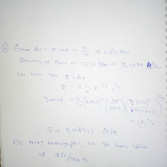
A system using 10-inch (10") internal diameter pipe requires a selection of flanged valves. Consider 10"...
 A system using 10-inch (10") internal diameter pipe requires a selection of flanged valves. Consider 10" ball valves, gate valves, globe valves, and check valves in the fully-open position; and butterfly valves in a variety of open positions. FNW has been chosen as the equipment supplier; the relevant data sheets can be found on Desire2Learn (see below for information on valve part numbers and cor- responding files). The data sheets give valve coefficients (C,): flow rates in GPM corresponding to...
 L 2. Steady statemass balance: Water is flowing at steady state in a 0.1 meter-diameter pipe with a maximum velocity (turbulent profile) of 0.3 meters/sec. The pipe then goes through an expansion, to where it is then flowing in a 0.5 meter-diameter pipe, and the flow regime has changed from turbulent to laminar. In the second section of pipe, calculate the velocity as (a) block flow profile (Vavg), and (b) maximum velocity in laminar flow profile? HINT: you will need...
 QUESTION 1 Water at 10 °C is flowing in a 90 bend pipe, with inner diameter of 150 mm, at an average velocity of 3.0 m/s and gauge pressure of 300 kPa. The pipe is laid in the horizontal plane as shown in figure below. The magnitude of the resultant (horizontal) force required to hold the bend in place is: a 5.46 kN b.7.72 kN Oc 10.92 kN d.5.15 kN . None of the other answers QUESTION 2 A 25.0...
 Question 1: Calculate the flow in each member of the pipe network shown in Figure 2.4 and also the presure difference in N/m' between C and iE. Data for the individual pipes is given in the table below. 360 Ve 300 V E 600 V 460 Va 100 Vs Figure 2.4 UET Pipe Length (m) Diameter (mm)Friction coefficient (l) 530 0.020 460 BC700 530 0.020 CD 610 600 0.022 DE601 600 0.018 EA 150 450 0.018 Hint: Assume initially that...
 CENTRE INDEX NUMBER SECTION B 30 marks] Calculate the discharge through a pipe of diameter 200 mm when the difference of pressure head between the ends of the pipe 500 m apart is 4 m of water. Take the value off= 0.009 in the formula hl= a) 19.5e/s b)2.0es e)03 m's d) 29.3 e/s 2. A scale 1:50 scale model of ship is towed through sea water at a speed of 1 ms. A force of 2 N is required...
 A system using 10-inch (10") internal diameter pipe requires a selection of flanged valves. Consider 10" ball valves, gate valves, globe valves, and check valves in the fully-open position; and butterfly valves in a variety of open positions. FNW has been chosen as the equipment supplier; the relevant data sheets can be found on Desire2Learn (see below for information on valve part numbers and cor- responding files). The data sheets give valve coefficients (C,): flow rates in GPM corresponding to...
Most questions answered within 3 hours.
-
Buying your in-laws a gift because it’s expected is
due to the ____________ motive of gift-giving....
asked 45 seconds from now -
Calculate the expected value, the variance, and the standard
deviation of the given random variable X....
asked 42 minutes ago -
A hospital performs 100 surgeries per week. The probability that
complications after surgery occur is 10%....
asked 58 minutes ago -
1 point) Given the significance level α=0.01 find the following:
(a) left-tailed z value z= (b)...
asked 40 minutes ago -
Assuming you are the head of the software development unit at
Cyber.Soft, explain and justify why...
asked 6 minutes ago -
Magnesium and nitrogen react in a combination reaction to
produce magnesium nitride. 3 Mg + N2...
asked 14 minutes ago -
Two electrons are initially at rest separated by a distance of
2nm. At time t=0, they...
asked 12 minutes ago -
A martial artist is practicing breaking 5 boards. He is able to
break aboard with probability...
asked 19 minutes ago -
The rate constant of a first-order reaction is 2.95 × 10⁻⁴ s−1
at 350.° C. If...
asked 22 minutes ago -
implement a class called PiggyBank that will be used to
represent a collection of coins. Functionality...
asked 13 minutes ago -
2. Use the following information in the table to answer the
following questions. (Numbers are in...
asked 19 minutes ago -
The fuel economy of a 2011 Lexus RX 350 2wd 6 cylinder 3.5 L
automatic 5...
asked 28 minutes ago