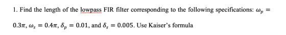

4. Consider the design of a windowed FIR lowpass filter corresponding to the specifications given in problem #1. Determine its length if Hann, Hamming, and Blackman windows are used. Hint: refer to Equation 10.36 and Table 10.2 of the textbook. 5. With reference to the specifications in problem #1, consider the design of an FIR lowpass filter using adjustable windows. Determine the filter orders corresponding to a) Dolph- Chebyshev window, and b) Kaiser window.
Figure 10.8: Relations among the fre windowed filter. quency responses of an ideal lowpass filter, a typical window, and the Table 10.2: Properties of some fixed window functions Type of Relative Sidelobe Level Ast 13.3 dB 26.5 dB 31.5 dB 42.7 dB 58.1 dB Main Lobe Width ΔML Minimum StopbandTransition Window Rectangular 4π/(201 + 1) Bartlett Hann Hamming 8T (2M 1) Blackman 12/(2M 1) Attenuation 20.9 dB See text 43.9 dB 54.5 dB 75.3 dB Bandwidth Ao 0.92T/M See text 3.11jr/M 3.32T/M 8/(2M 1) his table has been adapted from [Sar93], with the values shown in the table for oc 0.47 and M - Example 10.5 illustrates the effect of each of the above windows on the frequency response of an F lowpass filter designed using the windowed Fourier series approach ffect of Windows on the Frequency Response of an Ideal Lowpass Filter he impulse response hLP[n] of the ideal lowpass filter is given in Eq. (10.14). To create a finite- duration zero-phase FIR filter of length N , we form ht [n] = hLP[지-w[n], where M = (N 1)/2 Figure 10.9 shows the impulse response samples ht[n] for N 51 and ae-π/2. The gain response h various fixed It should be noted from this figure that the increase in h an increase in the transition in the sidelohe amnlitude results in an increase in the stopband attenuation. of each of the filters obtained by windowing the above impulse response samples wit window functions is sketched in Figure 10.10. the main lobe width of the window functions is clearly asso ciated wit
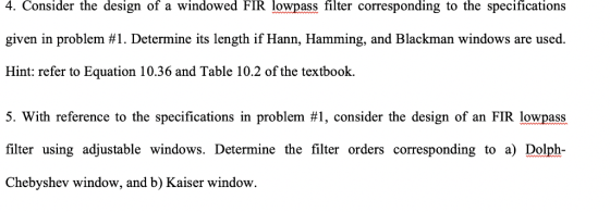
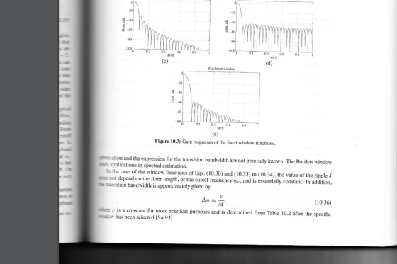
20 20 80 0.2 0.4 0.6 -l0OL 0.8 0.2 0.8 (i)/其 Blackman window 6D 0.2 0.6 0.8 Figure 10.7: Gain responses of the fixed window functions. tenuation and the expression for the transition bandwidth are not precisely known. The Bartlett window tinds applications in spectral estimation es not depend on the filter length, or the cutoff frequency de, te transition bandwidth is approximately given by the case of the window functions of Eqs. (10.30) and (10.33) to (10.34), the value of the ripple & and is essentially constant. In addition, (10.36) where c is a constant for most practical purposes and is determined from Table 10.2 after the specific window has been selected [Sar93]
Homework Answers
Add Answer to:
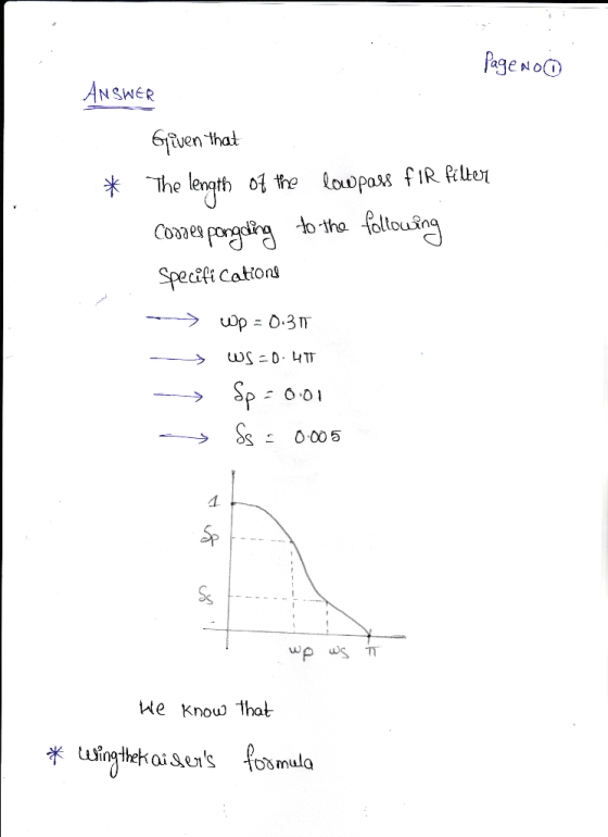
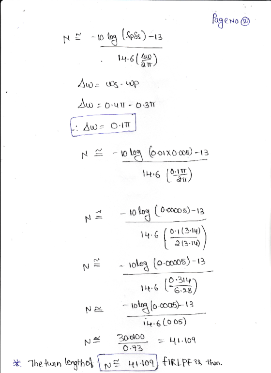
1. Find the length of the lowpass FIR filter corresponding to the following specifications: wp- 0...
0.09 Rect Bartlett Hann 21 26 0.0063 44 amming0.0022 53 74 M+1 M1 +1 M+1 0.05 12π ckman0.0002 Figure 2: The characteristics of the window types. . FIR filter design Using the windowing method, design...
 0.09 Rect Bartlett Hann 21 26 0.0063 44 amming0.0022 53 74 M+1 M1 +1 M+1 0.05 12π ckman0.0002 Figure 2: The characteristics of the window types. . FIR filter design Using the windowing method, design a causal linear-phase DT lowpass FIR filter with no more than 1 dB passband ripple at 16kHz, at least 50dB of attenuation at 20kHz, sampling rate of 400 kHz. Choose one of the windows in the table in Fig. 2. Select an even filter order...
Design a high pass FIR filter to meet the following specifications. Provide all equations needed to...
Design a high pass FIR filter to meet the following specifications. Provide all equations needed to produce the filter's impulse response. Pass band: 14.66 - 22 kHz Stop band rejection: min 40 dB Pass band ripple: max. 5% Sampling frquency: 48 kHz Use either a Hamming, Hann or Kaiser window. Derive the first three filter coefficients.
3. A length 21, FIR lowpass filter is designed using the windowing method, and rectan gular windo...
 3. A length 21, FIR lowpass filter is designed using the windowing method, and rectan gular window is employed. The ideal frequency response on which the design is based 1s given by If the filter's impulse response is 2πη sin 0
The MATLAB program below designs a lowpass filter for a passband edge frequency of 250Hz and...
 The MATLAB program below designs a lowpass filter for a passband edge frequency of 250Hz and a stopband edge of 350Hz. The sampling frequency is 2kHz. A Hamming window is used. (a) The program is on Webcampus. Run it and copy and paste the wvtool plots into Word. % FIR Filter Design (using wvtool) % Lowpass Design clear fpass 250; fstop 350; fs 2000; wp 2*pi* fpass/ fs; ws 2* pi fstop / fs; M=ceil(6.6 * pi / (ws-wp)) +...
Consider an FIR lowpass filter design with the following specifications: Passband Stopband Passband ripple Stopband attenuation...
 Consider an FIR lowpass filter design with the following
specifications:
Passband
Stopband
Passband ripple
Stopband attenuation
Sampling rate
Determine the following:
a. window method
b. length of the FIR filter
c. cutoff frequency for the design equation
We were unable to transcribe this imageWe were unable to transcribe this image= 1200 4000H = 0.1dB We were unable to transcribe this imageWe were unable to transcribe this image
Consider an FIR lowpass filter design with the following
specifications:
Passband
Stopband
Passband ripple
Stopband attenuation
Sampling rate
Determine the following:
a. window method
b. length of the FIR filter
c. cutoff frequency for the design equation
We were unable to transcribe this imageWe were unable to transcribe this image= 1200 4000H = 0.1dB We were unable to transcribe this imageWe were unable to transcribe this image
Using the windowing functions discussed in class, design a low-pass FIR filter with a cutoff freq...
 Using the windowing functions discussed in class, design a
low-pass FIR filter with a cutoff frequency of 2 kHz, a minimum
stop band attenuation of 40 dB, and a transition width of 200Hz.
The sampling frequency is 10kHz.
1. Using the windowing functions discussed in class, design a low-pass FIR filter with a cutoff frequency of 2 kHz, a minimum stop band attenuation of 40 dB, and a transition width of 200 Hz. The sampling frequency is 10 kHz 2....
Using the windowing functions discussed in class, design a
low-pass FIR filter with a cutoff frequency of 2 kHz, a minimum
stop band attenuation of 40 dB, and a transition width of 200Hz.
The sampling frequency is 10kHz.
1. Using the windowing functions discussed in class, design a low-pass FIR filter with a cutoff frequency of 2 kHz, a minimum stop band attenuation of 40 dB, and a transition width of 200 Hz. The sampling frequency is 10 kHz 2....
Design a linear-phase, bandpass FIR filter using the window-based approach to meet the following specifications: ws,L...
 Design a linear-phase, bandpass FIR filter using the window-based approach to meet the following specifications: ws,L = 0.3T,ap.L = 0.45T,Wp u = 0.65T, "Au-0.8T, mini- mum stopband at (i) Is there a unique window to meet the desired specifications? If not, choose the window with minimum transition width (ii) Plot the magnitude and phase response of the designed filter using MATLAB. (iii Using the MATLAB command firpm, design the same linear-phase bandpass FIR filter via the Parks-McClellan algorithm. Plot the...
1. It is desired to design a linear phase, length N FIR filter via the window method. The desired...
 1. It is desired to design a linear phase, length N FIR filter via the window method. The desired amplitude response is given by the function A(u), i.e Show how to calculate the filter coefficients h(n), n 0,1,..., N-1 from A(u) if the window function is wn
1. It is desired to design a linear phase, length N FIR filter via the window method. The desired amplitude response is given by the function A(u), i.e Show how to calculate the...
1. It is desired to design a linear phase, length N FIR filter via the window method. The desired amplitude response is given by the function A(u), i.e Show how to calculate the filter coefficients h(n), n 0,1,..., N-1 from A(u) if the window function is wn
1. It is desired to design a linear phase, length N FIR filter via the window method. The desired amplitude response is given by the function A(u), i.e Show how to calculate the...
NI+N2-1. Find the output y(n) by using the DFT and the inverse DFT method. 4. (20 points) Design a lowpass Butterworth filter with the following specifications: A desired peak passband ripple Rp...
 NI+N2-1. Find the output y(n) by using the DFT and the inverse DFT method. 4. (20 points) Design a lowpass Butterworth filter with the following specifications: A desired peak passband ripple Rp of 2 dB, the minimum stopband attenuation R, of 60 dB, the passband edge frequency op of 1000 rad/sec, and stopband edge frequency os of 3000 rad/sec (1) Estimate the order for this filter (2) Estimate the cut-off frequency for this filter. 5. (20 points) Consider the first-order...
Implementing a 3-Band Equaliser
Design and implement a 3-band equaliser using a DSP board or MPLab/CSS. The MATLAB Filter Designer could be used for filter design and graphing subject to the design requirements given below. This is an individual CW 2. Equaliser Primer An n-band equaliser is a device used to correct the frequency response characteristic of a signal processing system. Equalisers can be implemented using digital or analogue filters. The whole bandwidth of the equaliser is divided into n frequency bands, which can...
 0.09 Rect Bartlett Hann 21 26 0.0063 44 amming0.0022 53 74 M+1 M1 +1 M+1 0.05 12π ckman0.0002 Figure 2: The characteristics of the window types. . FIR filter design Using the windowing method, design a causal linear-phase DT lowpass FIR filter with no more than 1 dB passband ripple at 16kHz, at least 50dB of attenuation at 20kHz, sampling rate of 400 kHz. Choose one of the windows in the table in Fig. 2. Select an even filter order...
 3. A length 21, FIR lowpass filter is designed using the windowing method, and rectan gular window is employed. The ideal frequency response on which the design is based 1s given by If the filter's impulse response is 2πη sin 0
 The MATLAB program below designs a lowpass filter for a passband edge frequency of 250Hz and a stopband edge of 350Hz. The sampling frequency is 2kHz. A Hamming window is used. (a) The program is on Webcampus. Run it and copy and paste the wvtool plots into Word. % FIR Filter Design (using wvtool) % Lowpass Design clear fpass 250; fstop 350; fs 2000; wp 2*pi* fpass/ fs; ws 2* pi fstop / fs; M=ceil(6.6 * pi / (ws-wp)) +...
 Consider an FIR lowpass filter design with the following
specifications:
Passband
Stopband
Passband ripple
Stopband attenuation
Sampling rate
Determine the following:
a. window method
b. length of the FIR filter
c. cutoff frequency for the design equation
We were unable to transcribe this imageWe were unable to transcribe this image= 1200 4000H = 0.1dB We were unable to transcribe this imageWe were unable to transcribe this image
Consider an FIR lowpass filter design with the following
specifications:
Passband
Stopband
Passband ripple
Stopband attenuation
Sampling rate
Determine the following:
a. window method
b. length of the FIR filter
c. cutoff frequency for the design equation
We were unable to transcribe this imageWe were unable to transcribe this image= 1200 4000H = 0.1dB We were unable to transcribe this imageWe were unable to transcribe this image
 Using the windowing functions discussed in class, design a
low-pass FIR filter with a cutoff frequency of 2 kHz, a minimum
stop band attenuation of 40 dB, and a transition width of 200Hz.
The sampling frequency is 10kHz.
1. Using the windowing functions discussed in class, design a low-pass FIR filter with a cutoff frequency of 2 kHz, a minimum stop band attenuation of 40 dB, and a transition width of 200 Hz. The sampling frequency is 10 kHz 2....
Using the windowing functions discussed in class, design a
low-pass FIR filter with a cutoff frequency of 2 kHz, a minimum
stop band attenuation of 40 dB, and a transition width of 200Hz.
The sampling frequency is 10kHz.
1. Using the windowing functions discussed in class, design a low-pass FIR filter with a cutoff frequency of 2 kHz, a minimum stop band attenuation of 40 dB, and a transition width of 200 Hz. The sampling frequency is 10 kHz 2....
 Design a linear-phase, bandpass FIR filter using the window-based approach to meet the following specifications: ws,L = 0.3T,ap.L = 0.45T,Wp u = 0.65T, "Au-0.8T, mini- mum stopband at (i) Is there a unique window to meet the desired specifications? If not, choose the window with minimum transition width (ii) Plot the magnitude and phase response of the designed filter using MATLAB. (iii Using the MATLAB command firpm, design the same linear-phase bandpass FIR filter via the Parks-McClellan algorithm. Plot the...
 1. It is desired to design a linear phase, length N FIR filter via the window method. The desired amplitude response is given by the function A(u), i.e Show how to calculate the filter coefficients h(n), n 0,1,..., N-1 from A(u) if the window function is wn
1. It is desired to design a linear phase, length N FIR filter via the window method. The desired amplitude response is given by the function A(u), i.e Show how to calculate the...
1. It is desired to design a linear phase, length N FIR filter via the window method. The desired amplitude response is given by the function A(u), i.e Show how to calculate the filter coefficients h(n), n 0,1,..., N-1 from A(u) if the window function is wn
1. It is desired to design a linear phase, length N FIR filter via the window method. The desired amplitude response is given by the function A(u), i.e Show how to calculate the...
 NI+N2-1. Find the output y(n) by using the DFT and the inverse DFT method. 4. (20 points) Design a lowpass Butterworth filter with the following specifications: A desired peak passband ripple Rp of 2 dB, the minimum stopband attenuation R, of 60 dB, the passband edge frequency op of 1000 rad/sec, and stopband edge frequency os of 3000 rad/sec (1) Estimate the order for this filter (2) Estimate the cut-off frequency for this filter. 5. (20 points) Consider the first-order...
Most questions answered within 3 hours.
-
Calculate the equillibrium constent K for a redox reaction that
has E°cell = -.98 V at...
asked 10 minutes ago -
A concave spherical mirror has a radius of curvature of
magnitude 19.6 cm.
(a) Find the...
asked 12 minutes ago -
3. draw a diagram of the magnetic field:
a. around a long straight wire with a...
asked 11 minutes ago -
If you titrated 30.0 mL of 0.1 M HCl with 0.1 M NaOH, indicate
the approximate...
asked 19 minutes ago -
NADH passes electrons into the electron transport chain. List
the carriers that would receive the electrons,...
asked 27 minutes ago -
A cylindrical cable with a resistivity of 1.6x10⁻⁸ Ω·m and cross
sectional area of 3x10⁻⁵ m^2...
asked 27 minutes ago -
True or False.
A consumer with convex preferences who is indifferent between
the bundles (5,2) and...
asked 31 minutes ago -
A diamond's index of refraction for red light, 656 nm, is 2.410,
while that for blue...
asked 44 minutes ago -
Compare HPLC, SPE, and GC. Identify the differences, the
advantages, and the weaknesses of each method.
asked 45 minutes ago -
Characteristic x-rays emitted by potassium have a wavelength of
0.374 nm. What is the energy of...
asked 47 minutes ago -
there is a function to create two random numbers between 1 and
25 and a function...
asked 1 hour ago -
At a certain temperature, the ?pKp for the decomposition of
H2SH2S is 0.832.0.832.
H2S(g)↽−−⇀H2(g)+S(g)H2S(g)↽−−⇀H2(g)+S(g)
Initially, only...
asked 59 minutes ago