Learning Goal: To be able to identify the initial stresses and the angle of rotation, including the correct signs, and use these in the stress-transformation equations to find the stress on a plane or element at a different angle than the original. The method of calculating the state of stress on an inclined plane is tedious, prone to error, and incomplete—if we calculate σx′ and τx′y′, we have to do a separate calculation to determine σy′. Consider the stress element (a) shown in the picture below. (Figure 1) After being rotated through an angle θ, the stress elements σx′ and τx′y′ can be calculated by the inclined-plane method by letting the inclined plane be the y′ axis. (Figure 2) Balancing the sums of the forces in the primed coordinate system yields two equations: σx′=σxcos2θ+σysin2θ+τxy(2sinθcosθ) τx′y′=(σy−σx)sinθcosθ+τxy(cos2θ−sin2θ) Using the trigonometric identities 2sinθcosθ=sin(2θ), sin2θ=(1−cos(2θ))/2, and cos2θ=(1+cos(2θ))/2 and the fact that the +y′ axis is always 90∘ counterclockwise from the +x′ axis, we can derive the equations: σx′=σx+σy2+σx−σy2cos(2θ)+τxysin(2θ) σy′=σx+σy2−σx−σy2cos(2θ)−τxysin(2θ) τx′y′=−(σx−σy2)sin(2θ)+τxycos(2θ) These stress-transformation equations allow us to eliminate the geometric work that was involved in the incline-plane method of stress transformation and provides us with all three stresses in the primed coordinate system. In deriving these equations, we have used the standard sign convention that a normal stress, σ, is positive if it points outward from the stress element, a shear, τ, is positive if, on the face through with the +x axis passes, it points in the +y direction, and angles, θ∈(−180∘,180∘], are positive if they are counterclockwise from the +x axis.
figures numbered from left to right and bottom is 6th figure


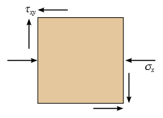

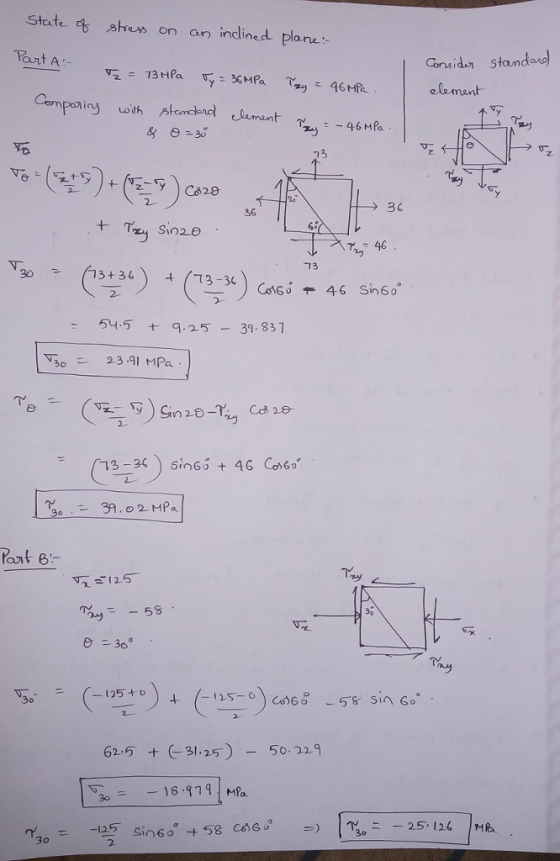
1. The state of stress at a point in a member is shown on the rectangular stress element below; the magnitudes of the stresses are |σx|=70 MPa,|σy|=36 MPa, and |τxy|=29 MPa.
(Figure 3)Using the stress-transformation equations, determine the state of stress on the inclined plane AB.
2. The state of stress at a point in a member is shown on the rectangular stress element below where the magnitudes of the stresses are |σx|=174 MPa and |τxy|=54 MPa.(Figure 4)
Determine the state of stress on an element rotated 40∘ clockwise from the element shown.
3. The state of stress at a point in a member is shown on the rectangular stress element below where the magnitudes of the stresses are |σx|=10 ksi,|σy|=29 ksi, and |τxy|=5 ksi.(Figure5)Determine the state of stress on an element rotated 60∘ counterclockwise from the element shown.
60° 15°
xi
Homework Answers

Add Answer to:
Learning Goal: To be able to identify the initial stresses and the angle of rotation, including t...
Question 1. For each of the plane-stress conditions given below, construct a Mohr’s circle of stress,...
Question 1. For each of the plane-stress conditions given below, construct a Mohr’s circle of stress, find the principal stresses and the orientation of the principal axes relative to the x,y axes and determine the stresses on an element, rotated in the x-y plane 60° counterclockwise from its original position: (a) σx = 200 MPa σy = 300 MPa τxy = - 40 MPa (b) σx = 500 MPa σy = -80 MPa τxy = 400 MPa Question 2. For...
Q3. (30 points) For the state of plane stress shown, Stresses, σ. σ2 (b) the orientation of the p...
 please help me solve this whole mechanical design
problem
thanks
Q3. (30 points) For the state of plane stress shown, Stresses, σ. σ2 (b) the orientation of the principal stresses, s, (c) the maximum in plane shearing stress, Tmar and (d) its orientation, p. (e) the normal stress at the plane of maximum shear stress, (1) sketch of the rotated plane element for the principal stresses and the rotated plane element for maximum shear stress similar to figure 1, below...
please help me solve this whole mechanical design
problem
thanks
Q3. (30 points) For the state of plane stress shown, Stresses, σ. σ2 (b) the orientation of the principal stresses, s, (c) the maximum in plane shearing stress, Tmar and (d) its orientation, p. (e) the normal stress at the plane of maximum shear stress, (1) sketch of the rotated plane element for the principal stresses and the rotated plane element for maximum shear stress similar to figure 1, below...
THE FOLLOWING PROBLEMS ARE TO BE SOLVED WITH A COMPUTER. Problem 1 A state of plane...
 THE FOLLOWING PROBLEMS ARE TO BE SOLVED WITH A COMPUTER. Problem 1 A state of plane stress is defined by the stress components 0, 0, and I associated with the element shown in Figure (a). i. Write a computer program that can be used to calculate the stress components 6, 5, and try" associated with the element after it has rotated through an angle about the z axis as shown in Figure (b). 1 F: Use this program to solve...
Learning Goal: To identify the directions of the shear and normal stresses in a simply supported...
 Learning Goal: To identify the directions of the shear and normal stresses in a simply supported straight beam subjected to a vertical point load. When a beam is subjected to both internal shear and bending moment, both normal and shear stresses will be developed within the beam. The normal stress at a point is related to the bending My moment by the flexure formula, o = where y is the I perpendicular distance of the point from the neutral axis....
hello guys can u help me :) Question 1. For each of the plane-stress conditions given...
 hello guys can u help me :)
Question 1. For each of the plane-stress conditions given below, using the matrix transformation law, determine the state of stress at the same point for an element rotated in the x-y plane 30° clockwise from its original position: (a) Ox = 200 MPa Oy = 400 MPa Txy = - 60 MPa (b) Ox = 300 MPa Oy = -180 MPa Txy = 320 MPa Question 2 my x2 The state of stress...
hello guys can u help me :)
Question 1. For each of the plane-stress conditions given below, using the matrix transformation law, determine the state of stress at the same point for an element rotated in the x-y plane 30° clockwise from its original position: (a) Ox = 200 MPa Oy = 400 MPa Txy = - 60 MPa (b) Ox = 300 MPa Oy = -180 MPa Txy = 320 MPa Question 2 my x2 The state of stress...
Part 7 To determine the normal and shear stresses on the indicated plane, we must first...
 Part 7
To determine the normal and shear stresses on the indicated
plane, we must first determine the orientation of the inclined
plane relative to the x face of the stress element.
Determine the magnitude of the clockwise angle θ between the
x face and the inclined plane.
Assume Sx = 80 ksi, Sy = 10
ksi, and Sxy = 12 ksi.
Part 8
For Mohr’s circle, all angular measures are doubled; therefore,
point n (which represents the state of...
Part 7
To determine the normal and shear stresses on the indicated
plane, we must first determine the orientation of the inclined
plane relative to the x face of the stress element.
Determine the magnitude of the clockwise angle θ between the
x face and the inclined plane.
Assume Sx = 80 ksi, Sy = 10
ksi, and Sxy = 12 ksi.
Part 8
For Mohr’s circle, all angular measures are doubled; therefore,
point n (which represents the state of...
The cylinder consists of spirally wrapped steel plates that are welded at the seams in the...
 The cylinder consists of spirally wrapped steel plates that are
welded at the seams in the orientation shown. Assume β = 30 ∘ . The
cylinder has an inside diameter of 31 in. and a wall thickness of
0.3125 in. The end of the cylinder is capped by a rigid end plate.
The cylinder is subjected to a compressive load of P = 115
kips and a torque of T = 255 kip-ft, which are applied to
the rigid end...
The cylinder consists of spirally wrapped steel plates that are
welded at the seams in the orientation shown. Assume β = 30 ∘ . The
cylinder has an inside diameter of 31 in. and a wall thickness of
0.3125 in. The end of the cylinder is capped by a rigid end plate.
The cylinder is subjected to a compressive load of P = 115
kips and a torque of T = 255 kip-ft, which are applied to
the rigid end...
tyles 3. For the body shown below a) Find the magnitude and orientation of the minor...
 tyles 3. For the body shown below a) Find the magnitude and orientation of the minor and major principal stresses relative to the base directions provided b) Find the maximum shear stress magnitude and orientation relative the x y axis c) Find the normal and shear stress state on the horizontal plane d) Find the normal and shear stress state on plane AB For a) through d) find the solution using I) the stress transform equations as determined from the...
Learning Goal: The beam shown (Figure 1) is supported by a pin at A and a...
 Learning Goal: The beam shown (Figure 1) is supported by a pin at A and a cable at B. Two loads P = 18 kN are applied straight down from the centerline of the bottom face. Determine the state of stress at the point shown (Figure 2) in a section 2 m from the wall. The dimensions are w = 5.4 cm , h = 12 cm, L = 0.8 m, a = 1.5 cm , and b = 4...
Figure 4 shows an element experiencing several stress components. Determine the following: 1. The stress components...
 Figure 4 shows an element experiencing several stress components. Determine the following: 1. The stress components Oxvxr. Oysy, and T xuy, acting on the element oriented at a counter clockwise angle = 40° from the horizontal x axis 2. The principal stresses, the maximum shear stress and their associated angles For each of the stress state calculated in parts 1 and 2, show all results on sketches of properly oriented elements. Note: Solutions MUST be obtained using Mohr's circle ONLY....
 please help me solve this whole mechanical design
problem
thanks
Q3. (30 points) For the state of plane stress shown, Stresses, σ. σ2 (b) the orientation of the principal stresses, s, (c) the maximum in plane shearing stress, Tmar and (d) its orientation, p. (e) the normal stress at the plane of maximum shear stress, (1) sketch of the rotated plane element for the principal stresses and the rotated plane element for maximum shear stress similar to figure 1, below...
please help me solve this whole mechanical design
problem
thanks
Q3. (30 points) For the state of plane stress shown, Stresses, σ. σ2 (b) the orientation of the principal stresses, s, (c) the maximum in plane shearing stress, Tmar and (d) its orientation, p. (e) the normal stress at the plane of maximum shear stress, (1) sketch of the rotated plane element for the principal stresses and the rotated plane element for maximum shear stress similar to figure 1, below...
 THE FOLLOWING PROBLEMS ARE TO BE SOLVED WITH A COMPUTER. Problem 1 A state of plane stress is defined by the stress components 0, 0, and I associated with the element shown in Figure (a). i. Write a computer program that can be used to calculate the stress components 6, 5, and try" associated with the element after it has rotated through an angle about the z axis as shown in Figure (b). 1 F: Use this program to solve...
 Learning Goal: To identify the directions of the shear and normal stresses in a simply supported straight beam subjected to a vertical point load. When a beam is subjected to both internal shear and bending moment, both normal and shear stresses will be developed within the beam. The normal stress at a point is related to the bending My moment by the flexure formula, o = where y is the I perpendicular distance of the point from the neutral axis....
 hello guys can u help me :)
Question 1. For each of the plane-stress conditions given below, using the matrix transformation law, determine the state of stress at the same point for an element rotated in the x-y plane 30° clockwise from its original position: (a) Ox = 200 MPa Oy = 400 MPa Txy = - 60 MPa (b) Ox = 300 MPa Oy = -180 MPa Txy = 320 MPa Question 2 my x2 The state of stress...
hello guys can u help me :)
Question 1. For each of the plane-stress conditions given below, using the matrix transformation law, determine the state of stress at the same point for an element rotated in the x-y plane 30° clockwise from its original position: (a) Ox = 200 MPa Oy = 400 MPa Txy = - 60 MPa (b) Ox = 300 MPa Oy = -180 MPa Txy = 320 MPa Question 2 my x2 The state of stress...
 Part 7
To determine the normal and shear stresses on the indicated
plane, we must first determine the orientation of the inclined
plane relative to the x face of the stress element.
Determine the magnitude of the clockwise angle θ between the
x face and the inclined plane.
Assume Sx = 80 ksi, Sy = 10
ksi, and Sxy = 12 ksi.
Part 8
For Mohr’s circle, all angular measures are doubled; therefore,
point n (which represents the state of...
Part 7
To determine the normal and shear stresses on the indicated
plane, we must first determine the orientation of the inclined
plane relative to the x face of the stress element.
Determine the magnitude of the clockwise angle θ between the
x face and the inclined plane.
Assume Sx = 80 ksi, Sy = 10
ksi, and Sxy = 12 ksi.
Part 8
For Mohr’s circle, all angular measures are doubled; therefore,
point n (which represents the state of...
 The cylinder consists of spirally wrapped steel plates that are
welded at the seams in the orientation shown. Assume β = 30 ∘ . The
cylinder has an inside diameter of 31 in. and a wall thickness of
0.3125 in. The end of the cylinder is capped by a rigid end plate.
The cylinder is subjected to a compressive load of P = 115
kips and a torque of T = 255 kip-ft, which are applied to
the rigid end...
The cylinder consists of spirally wrapped steel plates that are
welded at the seams in the orientation shown. Assume β = 30 ∘ . The
cylinder has an inside diameter of 31 in. and a wall thickness of
0.3125 in. The end of the cylinder is capped by a rigid end plate.
The cylinder is subjected to a compressive load of P = 115
kips and a torque of T = 255 kip-ft, which are applied to
the rigid end...
 tyles 3. For the body shown below a) Find the magnitude and orientation of the minor and major principal stresses relative to the base directions provided b) Find the maximum shear stress magnitude and orientation relative the x y axis c) Find the normal and shear stress state on the horizontal plane d) Find the normal and shear stress state on plane AB For a) through d) find the solution using I) the stress transform equations as determined from the...
 Learning Goal: The beam shown (Figure 1) is supported by a pin at A and a cable at B. Two loads P = 18 kN are applied straight down from the centerline of the bottom face. Determine the state of stress at the point shown (Figure 2) in a section 2 m from the wall. The dimensions are w = 5.4 cm , h = 12 cm, L = 0.8 m, a = 1.5 cm , and b = 4...
 Figure 4 shows an element experiencing several stress components. Determine the following: 1. The stress components Oxvxr. Oysy, and T xuy, acting on the element oriented at a counter clockwise angle = 40° from the horizontal x axis 2. The principal stresses, the maximum shear stress and their associated angles For each of the stress state calculated in parts 1 and 2, show all results on sketches of properly oriented elements. Note: Solutions MUST be obtained using Mohr's circle ONLY....
Most questions answered within 3 hours.
-
Japan’s combination of X and Y
Canada’s combination of X and Y
100x and 0y
50x...
asked 2 minutes ago -
Determine the temperature (in Celsius) at which 1.00 mole of an
ideal gas will have a...
asked 9 minutes ago -
[1] Household statistics include individuals living alone or in
groups in:
A) apartments.
B) military barracks....
asked 12 minutes ago -
What is the % w/v when 80 mL of a 2.0% solution is mixed with 50...
asked 16 minutes ago -
How can I solve the following using a TI83
Claim: Most adults would erase all of...
asked 29 minutes ago -
Analysis of 3-ethyl-3-buten-2-ol gave C, 72.13%; H, 11.92%.
Calculate the percent deviation of these results from...
asked 26 minutes ago -
Which VALS segment is most likely to have a top of the line
brand new (2015)...
asked 30 minutes ago -
Write a program to score the paper-rock-scissor game. Each of
two users types in either P,R...
asked 50 minutes ago -
Calculate the equillibrium constent K for a redox reaction that
has E°cell = -.98 V at...
asked 1 hour ago -
A concave spherical mirror has a radius of curvature of
magnitude 19.6 cm.
(a) Find the...
asked 1 hour ago -
3. draw a diagram of the magnetic field:
a. around a long straight wire with a...
asked 1 hour ago -
If you titrated 30.0 mL of 0.1 M HCl with 0.1 M NaOH, indicate
the approximate...
asked 1 hour ago