
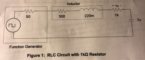

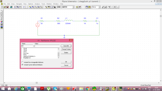
Inductor 50 300 220m 1k Function Generator Figure 1: RLC Circuit with 1kQ Resistor
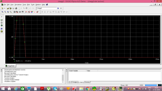
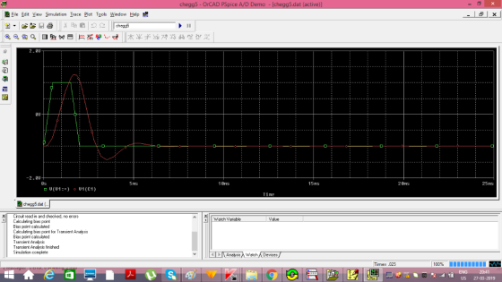
Generate a computer simulation modeling the capacitor voltage transient of the RLC circuit for Figures 1 and 2. Measure the initial capacitor voltage, vc(0), the final capacitor voltage, vc), and the capacitor voltage at 0.5 mS, 1 mS, and 2 mS. Record your values in the appropriate sections of Tables 1 and 3. Include a screenshot of the schematic and a screenshot of the transient analysis and compare any difference between your pre-lab, simulation, and experimental results in your lab write-up for all five values in each of the three scenarios (including the resistor voltage scenario described below). Generate a computer simulation modeling the resistor voltage transient of the RLC circuit in Figure 2. Measure the initial resistor voltage, vR(0), the final resistor voltage, esistor voltage at 0.5 mS, 1 mS and 2 mS. Record your values in the appropriate sections of Table 2.
Homework Answers
ASSUMPTION:
1. The function generator is continuous
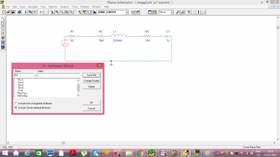
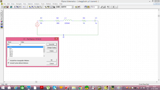
PARAMETERS OF FUNCTION GENERATOR ARE AS FOLLOWS
A. V1=+1
B. V2=-1
C. TD= 0 , delay in voltage
D. Tr= 0 ,rise time
E. Tf=0 , fall time
F. Tw=1ms , width of voltage V2
E. PER = 4ms , time period for 1 pulse
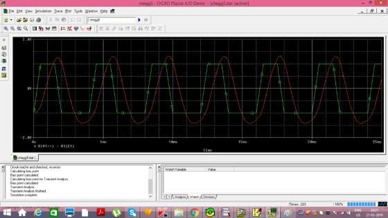
t=0 Vc=-1v
t=0.5ms Vc=-0.5v
t=1ms Vc= 0.25v
t=2ms Vc= 1v
 TABLE
TABLE
t=0s Vr=-1
t=0.5ms Vr= 0
t=1ms Vr= -1
t=2ms Vr = -2
ASSUMPTION FOR SINGLE PULSE

Add Answer to:
Inductor +VR 300 220m 100 50 LI Function Generator Figure 2: RLC Circuit with 100Ω Resistor Ind...
Function Generatr Inductor Model Ra R, Figure 1 Series RLC Circuit Preliminary This laboratory wi...
 Function Generatr Inductor Model Ra R, Figure 1 Series RLC Circuit Preliminary This laboratory will demonstrate how varying resistance changes the natural response of a series RLC circuit (Fig. 1). The function generator is modeled as an ideal voltage source v(t) 5 u() V in series with source resistance Rs-50Q. After measurements using an LCR meter, the inductor is modeled as an ideal L 90 mH inductor in series with resistance RL-20Q. The capacitance is C-0.22 μF. 1) Calculate the...
in a certain RLC circuit, a 32- resistor, a 18-mH inductor, and a 5-F capacitor are...
 in a certain RLC circuit, a 32- resistor, a 18-mH inductor, and a 5-F capacitor are connected in series with an AC power source for which V -16 Vand f = 100 Hz. (a) Calculate the amplitude of the current, (b) Calculate the phase between the current and the voltage, (c) Calculate the maximum voltage across each component. {0.0733 A. -1.47 rad, VR-2.35 V, Vc = 23.3 V, V.- 0.829 V?
What are the Equilibrium voltages of the capacitor and the resistor when the function generator v...
 What are the Equilibrium voltages of the capacitor and the
resistor when the function generator voltage is +v0? Is this what
you observe on your oscilloscope sketches?
what are the equilibrium voltages of the capacitor and the resistor when the function generator voltage is ± you observe on your oscilloscope sketches? ? Is this what An RC circuit consists of a resistor connected to a capacitor. There may also be a fixed power supply, depending on whether the capacitor is...
What are the Equilibrium voltages of the capacitor and the
resistor when the function generator voltage is +v0? Is this what
you observe on your oscilloscope sketches?
what are the equilibrium voltages of the capacitor and the resistor when the function generator voltage is ± you observe on your oscilloscope sketches? ? Is this what An RC circuit consists of a resistor connected to a capacitor. There may also be a fixed power supply, depending on whether the capacitor is...
Consider the simple series RLC circuit shown in figure below, the circuit has the following parameters,...
 Consider the simple series RLC circuit shown in figure below, the circuit has the following parameters, R=12, L = 0.2 Henry, and C = 0.05 Farad, R 1000 Vs The system is governed by the following equations: V = VR + V + V VR = IR V = Vc S(t)dt Or I = CM Construct a Simulink model for this system such that the input is the supply voltage Vs and the output is the voltage across the resistor...
2. Charge-up response of series RLC circuit. No energy is stored in the 0.1H inductor or...
 2. Charge-up response of series RLC circuit. No energy is stored in the 0.1H inductor or the 0.4uF capacitor before the switch in the circuit shown in the figure below is closed. Find S2 Key= A 2800 1. 0.4uF - 3. Discharge response of series RLC circuit. The circuit had been in steady state prior to moving the switch at t=0. Find = Key = Space Key C1 0.44F For both circuits: a) Is the response underdamped, overdamped, or critically...
2) An RLC series circuit with 150-ohm resistor, 25-mH inductor, and 2 microfarad-capacitor is powered by...
2) An RLC series circuit with 150-ohm resistor, 25-mH inductor, and 2 microfarad-capacitor is powered by an AC voltage source with a peak voltage of 340V and a frequency of 660 Hz. (a) Find the peak current that flows in the circuit. (b) Determine the phase angle of the source voltage relative to the current. (c) Determine the peak voltage across the resistor and its phase angle relative to the voltage source. (d) Find the peak voltage across the inductor...
An RLC series circuit with 150-ohm resistor, 25-mH inductor, and 2 microfarad-capacitor is powered by an...
An RLC series circuit with 150-ohm resistor, 25-mH inductor, and 2 microfarad-capacitor is powered by an AC voltage source with a peak voltage of 340V and a frequency of 660 Hz. (a) Find the peak current that flows in the circuit. (b) Determine the phase angle of the source voltage relative to the current. (c) Determine the peak voltage across the resistor and its phase angle relative to the voltage source. (d) Find the peak voltage across the inductor and...
2) An RLC series circuit with 150-ohm resistor, 25-mH inductor, and 2 microfarad-capacitor is powered by...
 2) An RLC series circuit with 150-ohm resistor, 25-mH inductor, and 2 microfarad-capacitor is powered by an AC voltage source with a peak voltage of 340V and a frequency of 660 Hz. (a) Find the peak current that flows in the circuit. (b) Determine the phase angle of the source voltage relative to the current. (c) Determine the peak voltage across the resistor and its phase angle relative to the voltage source. (d) Find the peak voltage across the inductor...
A circuit is constructed with an AC generator, a resistor, capacitor and inductor as shown. The...
 A circuit is constructed with an AC generator,
a resistor, capacitor and inductor as shown. The generator voltage
varies in time as ? =Va - Vb =
?msin?t, where
?m = 120 V and ? =
221 radians/second. The inductance L = 352 mH. The values for the
capacitance C and the resistance R are unkown. What is known is
that the current in the circuit leads the voltage across the
generator by ? = 58 degrees and the average...
A circuit is constructed with an AC generator,
a resistor, capacitor and inductor as shown. The generator voltage
varies in time as ? =Va - Vb =
?msin?t, where
?m = 120 V and ? =
221 radians/second. The inductance L = 352 mH. The values for the
capacitance C and the resistance R are unkown. What is known is
that the current in the circuit leads the voltage across the
generator by ? = 58 degrees and the average...
 Function Generatr Inductor Model Ra R, Figure 1 Series RLC Circuit Preliminary This laboratory will demonstrate how varying resistance changes the natural response of a series RLC circuit (Fig. 1). The function generator is modeled as an ideal voltage source v(t) 5 u() V in series with source resistance Rs-50Q. After measurements using an LCR meter, the inductor is modeled as an ideal L 90 mH inductor in series with resistance RL-20Q. The capacitance is C-0.22 μF. 1) Calculate the...
 in a certain RLC circuit, a 32- resistor, a 18-mH inductor, and a 5-F capacitor are connected in series with an AC power source for which V -16 Vand f = 100 Hz. (a) Calculate the amplitude of the current, (b) Calculate the phase between the current and the voltage, (c) Calculate the maximum voltage across each component. {0.0733 A. -1.47 rad, VR-2.35 V, Vc = 23.3 V, V.- 0.829 V?
 What are the Equilibrium voltages of the capacitor and the
resistor when the function generator voltage is +v0? Is this what
you observe on your oscilloscope sketches?
what are the equilibrium voltages of the capacitor and the resistor when the function generator voltage is ± you observe on your oscilloscope sketches? ? Is this what An RC circuit consists of a resistor connected to a capacitor. There may also be a fixed power supply, depending on whether the capacitor is...
What are the Equilibrium voltages of the capacitor and the
resistor when the function generator voltage is +v0? Is this what
you observe on your oscilloscope sketches?
what are the equilibrium voltages of the capacitor and the resistor when the function generator voltage is ± you observe on your oscilloscope sketches? ? Is this what An RC circuit consists of a resistor connected to a capacitor. There may also be a fixed power supply, depending on whether the capacitor is...
 Consider the simple series RLC circuit shown in figure below, the circuit has the following parameters, R=12, L = 0.2 Henry, and C = 0.05 Farad, R 1000 Vs The system is governed by the following equations: V = VR + V + V VR = IR V = Vc S(t)dt Or I = CM Construct a Simulink model for this system such that the input is the supply voltage Vs and the output is the voltage across the resistor...
 2. Charge-up response of series RLC circuit. No energy is stored in the 0.1H inductor or the 0.4uF capacitor before the switch in the circuit shown in the figure below is closed. Find S2 Key= A 2800 1. 0.4uF - 3. Discharge response of series RLC circuit. The circuit had been in steady state prior to moving the switch at t=0. Find = Key = Space Key C1 0.44F For both circuits: a) Is the response underdamped, overdamped, or critically...
 2) An RLC series circuit with 150-ohm resistor, 25-mH inductor, and 2 microfarad-capacitor is powered by an AC voltage source with a peak voltage of 340V and a frequency of 660 Hz. (a) Find the peak current that flows in the circuit. (b) Determine the phase angle of the source voltage relative to the current. (c) Determine the peak voltage across the resistor and its phase angle relative to the voltage source. (d) Find the peak voltage across the inductor...
 A circuit is constructed with an AC generator,
a resistor, capacitor and inductor as shown. The generator voltage
varies in time as ? =Va - Vb =
?msin?t, where
?m = 120 V and ? =
221 radians/second. The inductance L = 352 mH. The values for the
capacitance C and the resistance R are unkown. What is known is
that the current in the circuit leads the voltage across the
generator by ? = 58 degrees and the average...
A circuit is constructed with an AC generator,
a resistor, capacitor and inductor as shown. The generator voltage
varies in time as ? =Va - Vb =
?msin?t, where
?m = 120 V and ? =
221 radians/second. The inductance L = 352 mH. The values for the
capacitance C and the resistance R are unkown. What is known is
that the current in the circuit leads the voltage across the
generator by ? = 58 degrees and the average...
Most questions answered within 3 hours.
-
The free energy change for the following reaction at 25 °C, when
[Sn2+] = 1.17 M...
asked 1 hour ago -
An MNE is this kind of industry when competition in one country
is essentially independent of...
asked 3 hours ago -
. For this set of questions, determine what
proportion of a normal distribution is located betweeneach...
asked 3 hours ago -
A college student is employed as a door-to-door newspaper
salesman. Historical data suggests that the student...
asked 4 hours ago -
MATLAB HW 11 problem using Switch Case and Input commands
Write a script file that calculates...
asked 4 hours ago -
Considering gravitational time dilation, calculate the time that
passes in Earth’s surface while 1 hour passes...
asked 5 hours ago -
Minitab Problem: Take the Lake Hume June rainfall data and find
use the processes outlined in...
asked 5 hours ago -
X Company is trying to decide whether to continue using old
equipment to make Product A...
asked 5 hours ago -
IN PYTHON ONLY !! Program 2: Re-work
program #5 (WeeklyHours) from the previous assignment such that...
asked 6 hours ago -
The average length of time between arrivals at a turnpike
toll-booth is 26 seconds. What is...
asked 8 hours ago -
(a) A piston at 6.1 atm contains a gas that occupies a volume of
3.5 L....
asked 9 hours ago -
Please answer true or false. Words
cannot be changed or added in to make it true...
asked 9 hours ago