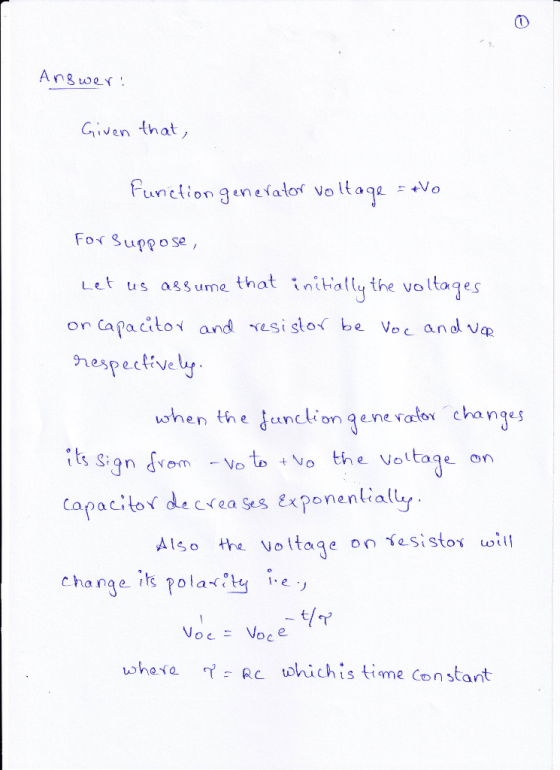
What are the Equilibrium voltages of the capacitor and the
resistor when the function generator voltage is +v0? Is this what
you observe on your oscilloscope sketches?


An RC circuit consists of a resistor connected to a capacitor. There may also be a fixed power supply, depending on whether the capacitor is being charged or discharged.1 In this lab, rather than using a power supply to charge and discharge the capacitor, we will be using an input of a square wave voltage, which oscillates between some voltage Vo and -Vo (which depends on on the amplitude you set). This will repeatedly charge the capacitor one way, then the other, with currents passing through the resistor each time We will denote the input voltage from the function generator as Vfc(t), the voltage across the capacitor as Vc(t), and the voltage across the resistor as VR(t) We treat "positive" as from the high side of the function generator to the low side, which implies (by Kirchhoff's Voltage Law) VFG(t) VR(t) Vc(t) We also know that VR (t)I(t)R (Ohm's law) and Vc(t)Q(t)/C (definition of capacitance) Although the details of amplitudes are slightly different than a purely discharging capacitor, one still observes an exponential decay to the equilibrium voltage, with the same time constant: We will make measurements, for both the capacitor and the resistor, of the difference between the voltage across the component and the equilibrium voltage across the component. That is to say, if the capacitor approaches an equilibrium voltage of Vc,eq, then we will measure Vc(t) - Vc,eg (and similarly for the resistor) Call this quantity Vaiff(t). Then, for both the resistor and the capacitor, we expect the relationship (with some initial voltage V): diff There is a practical issue with this from our perspective, however: this is a nonlinear relationship, so our plotting tool cannot infer T from a slope! Therefore, we apply a trick: we make a log-linear plot. By taking a logarithm of both sides of (2), we can reduce this to the equation This means that if we plot In(Viff) vs. t, we will get a linear plot (with intercept), and can infer T from the slope. Problem solved!
Homework Answers

Add Answer to:
What are the Equilibrium voltages of the capacitor and the resistor when the function generator v...
Inductor +VR 300 220m 100 50 LI Function Generator Figure 2: RLC Circuit with 100Ω Resistor Ind...
 Please help answer in pspice, thank you very much.
Inductor +VR 300 220m 100 50 LI Function Generator Figure 2: RLC Circuit with 100Ω Resistor Inductor 50 300 220m 1k Function Generator Figure 1: RLC Circuit with 1kQ Resistor Generate a computer simulation modeling the capacitor voltage transient of the RLC circuit for Figures 1 and 2. Measure the initial capacitor voltage, vc(0), the final capacitor voltage, vc), and the capacitor voltage at 0.5 mS, 1 mS, and 2 mS....
Please help answer in pspice, thank you very much.
Inductor +VR 300 220m 100 50 LI Function Generator Figure 2: RLC Circuit with 100Ω Resistor Inductor 50 300 220m 1k Function Generator Figure 1: RLC Circuit with 1kQ Resistor Generate a computer simulation modeling the capacitor voltage transient of the RLC circuit for Figures 1 and 2. Measure the initial capacitor voltage, vc(0), the final capacitor voltage, vc), and the capacitor voltage at 0.5 mS, 1 mS, and 2 mS....
3. (Bonus) Determine a state variable model for the circuit in Figure 2. Note that If the voltage...
 3. (Bonus) Determine a state variable model for the circuit in Figure 2. Note that If the voltage at the left and right hand side of a resistor R is v and vR, respectively, and the current is assumed to flow through the resistor from left to right, then the current passing through the resistor R is iR We know that the voltage drop across a capacitor is uc = the current passing through the capacitor branch is ic cat,...
1. Using circuit 3-1, calculate the total current (which is also the capacitor current and resistor...
 1. Using circuit 3-1, calculate the total current (which is also
the capacitor current and resistor current) by using Ohm’s Law. To
do this, you must first compute the total impedance of the circuit,
in polar form. Also, remember that Vs (source voltage) phase shift
is 0 degrees. Write your answer in polar form.
2. Compute the voltage across the capacitor (C1), using Ohm’s
Law and your result from #1. Write your answer in polar form.
3. In a series...
1. Using circuit 3-1, calculate the total current (which is also
the capacitor current and resistor current) by using Ohm’s Law. To
do this, you must first compute the total impedance of the circuit,
in polar form. Also, remember that Vs (source voltage) phase shift
is 0 degrees. Write your answer in polar form.
2. Compute the voltage across the capacitor (C1), using Ohm’s
Law and your result from #1. Write your answer in polar form.
3. In a series...
I am currently trying to figure out the experiment below. Please complete Table 1 with an...
 I am currently trying to figure out the experiment below. Please
complete Table 1 with an explanation, I appreciate it thank
you! Promise to give thumbs up!
Introduction The phase differences between the output voltage, the voltage across the inductor, the voltage across the capacitor, and the voltage across the resistor will be examined at resonant frequency. The voltage and phase relationship will also be examined for frequencies above and below resonance. Theory An inductor, a capacitor, and a resistor are...
I am currently trying to figure out the experiment below. Please
complete Table 1 with an explanation, I appreciate it thank
you! Promise to give thumbs up!
Introduction The phase differences between the output voltage, the voltage across the inductor, the voltage across the capacitor, and the voltage across the resistor will be examined at resonant frequency. The voltage and phase relationship will also be examined for frequencies above and below resonance. Theory An inductor, a capacitor, and a resistor are...
Construct a RC circuit (series) with a capacitor, a resistor, a battery,
 Part A Charging of RC Circuit 1) Construct a RC circuit (series) with a capacitor, a resistor, a battery, two switches, and appropriate meters that will enable you to make measurements of the parameters for charging up the capacitor. The placement of the switches allows you to measure both charging and discharging of the RC circuit. See diagram below: 2) Choose a combination of Rand C that will give you a time constant(T) of 20 seconds. T=R*C 20= 100* C=0.2F 3) Set the...
B oth 100 Day PH262 Page 1 of 5 Lab #13 AC Circuits, Part 1 RC...
 B oth 100 Day PH262 Page 1 of 5 Lab #13 AC Circuits, Part 1 RC & RL, Phase Measurements THEORY The rotating phase representation for series AC circuits should be familiar from textbook and lecture notes A brief outline of the essential points is provided here. If a series RLC circuit is connected across a source of om which is a sinusoidal function of time, then und all its derivatives will also be inside. Sonce all demits in a...
1. Why can the DSO only measure node voltages when the Function Generator is the power supply in ...
 1. Why can the DSO only measure node voltages when the Function Generator is the power supply in a circuit (unless it is using a current probe)? 2. Consider Figure 1. According to the calculations in the lab handout, if Z-1kΩ +/6914, then the phase difference (фи-фі) between u(t) and i (t) is 34.6". a. If this v(t) and i(t) were displayed on a DSO (v(t) being a node voltage and using a current probe for i(t) as shown in...
I just need help with parts d and e and what equation i would use to...
 I just need help with parts d and e and what equation i would
use to make my graph
7. The input voltage for the circuit shown in Figure 6.22 is given by Vc(t)- Vo cos ot. Figure 6.22. Circuit for Problem 7 (a) Find the equivalent impedance of all three components in the complex notation. (b) What is the expression for amplitude of the current? (c) What is the expression for the phase difference between the current and the...
I just need help with parts d and e and what equation i would
use to make my graph
7. The input voltage for the circuit shown in Figure 6.22 is given by Vc(t)- Vo cos ot. Figure 6.22. Circuit for Problem 7 (a) Find the equivalent impedance of all three components in the complex notation. (b) What is the expression for amplitude of the current? (c) What is the expression for the phase difference between the current and the...
(written portion due 5/7/2019) Inductor and a Resistor in parallel A circuit with two resistors has...
 (written portion due 5/7/2019) Inductor and a Resistor in parallel A circuit with two resistors has one junction in it. The split has a resistor on one side and an inductor on the other a) Show a sketch of what the current in the inductor as a function of time and propose an equation that fits the plot. The solution should have a signature time in it. b) Using the junction rule, plot a sketch of what the current in...
12. A series RC circuit is driven by a periodic square wave voltage V(t) with a period T=0.3 sec. V(t)0 for t<0. Aft...
 12. A series RC circuit is driven by a periodic square wave voltage V(t) with a period T=0.3 sec. V(t)0 for t<0. After t=0, the voltage alternates between 15 V and 0 V. Assume that R-40 , C-150 HF. We will call the voltage across the capacitor and the resistor Ve(t and Vr(t) respectively (a) Calculate the current I(t) in the circuit, the voltage Vc(t), and the power delivered by the driving source as a function of time for the...
 Please help answer in pspice, thank you very much.
Inductor +VR 300 220m 100 50 LI Function Generator Figure 2: RLC Circuit with 100Ω Resistor Inductor 50 300 220m 1k Function Generator Figure 1: RLC Circuit with 1kQ Resistor Generate a computer simulation modeling the capacitor voltage transient of the RLC circuit for Figures 1 and 2. Measure the initial capacitor voltage, vc(0), the final capacitor voltage, vc), and the capacitor voltage at 0.5 mS, 1 mS, and 2 mS....
Please help answer in pspice, thank you very much.
Inductor +VR 300 220m 100 50 LI Function Generator Figure 2: RLC Circuit with 100Ω Resistor Inductor 50 300 220m 1k Function Generator Figure 1: RLC Circuit with 1kQ Resistor Generate a computer simulation modeling the capacitor voltage transient of the RLC circuit for Figures 1 and 2. Measure the initial capacitor voltage, vc(0), the final capacitor voltage, vc), and the capacitor voltage at 0.5 mS, 1 mS, and 2 mS....
 3. (Bonus) Determine a state variable model for the circuit in Figure 2. Note that If the voltage at the left and right hand side of a resistor R is v and vR, respectively, and the current is assumed to flow through the resistor from left to right, then the current passing through the resistor R is iR We know that the voltage drop across a capacitor is uc = the current passing through the capacitor branch is ic cat,...
 1. Using circuit 3-1, calculate the total current (which is also
the capacitor current and resistor current) by using Ohm’s Law. To
do this, you must first compute the total impedance of the circuit,
in polar form. Also, remember that Vs (source voltage) phase shift
is 0 degrees. Write your answer in polar form.
2. Compute the voltage across the capacitor (C1), using Ohm’s
Law and your result from #1. Write your answer in polar form.
3. In a series...
1. Using circuit 3-1, calculate the total current (which is also
the capacitor current and resistor current) by using Ohm’s Law. To
do this, you must first compute the total impedance of the circuit,
in polar form. Also, remember that Vs (source voltage) phase shift
is 0 degrees. Write your answer in polar form.
2. Compute the voltage across the capacitor (C1), using Ohm’s
Law and your result from #1. Write your answer in polar form.
3. In a series...
 I am currently trying to figure out the experiment below. Please
complete Table 1 with an explanation, I appreciate it thank
you! Promise to give thumbs up!
Introduction The phase differences between the output voltage, the voltage across the inductor, the voltage across the capacitor, and the voltage across the resistor will be examined at resonant frequency. The voltage and phase relationship will also be examined for frequencies above and below resonance. Theory An inductor, a capacitor, and a resistor are...
I am currently trying to figure out the experiment below. Please
complete Table 1 with an explanation, I appreciate it thank
you! Promise to give thumbs up!
Introduction The phase differences between the output voltage, the voltage across the inductor, the voltage across the capacitor, and the voltage across the resistor will be examined at resonant frequency. The voltage and phase relationship will also be examined for frequencies above and below resonance. Theory An inductor, a capacitor, and a resistor are...
 Part A Charging of RC Circuit 1) Construct a RC circuit (series) with a capacitor, a resistor, a battery, two switches, and appropriate meters that will enable you to make measurements of the parameters for charging up the capacitor. The placement of the switches allows you to measure both charging and discharging of the RC circuit. See diagram below: 2) Choose a combination of Rand C that will give you a time constant(T) of 20 seconds. T=R*C 20= 100* C=0.2F 3) Set the...
 B oth 100 Day PH262 Page 1 of 5 Lab #13 AC Circuits, Part 1 RC & RL, Phase Measurements THEORY The rotating phase representation for series AC circuits should be familiar from textbook and lecture notes A brief outline of the essential points is provided here. If a series RLC circuit is connected across a source of om which is a sinusoidal function of time, then und all its derivatives will also be inside. Sonce all demits in a...
 1. Why can the DSO only measure node voltages when the Function Generator is the power supply in a circuit (unless it is using a current probe)? 2. Consider Figure 1. According to the calculations in the lab handout, if Z-1kΩ +/6914, then the phase difference (фи-фі) between u(t) and i (t) is 34.6". a. If this v(t) and i(t) were displayed on a DSO (v(t) being a node voltage and using a current probe for i(t) as shown in...
 I just need help with parts d and e and what equation i would
use to make my graph
7. The input voltage for the circuit shown in Figure 6.22 is given by Vc(t)- Vo cos ot. Figure 6.22. Circuit for Problem 7 (a) Find the equivalent impedance of all three components in the complex notation. (b) What is the expression for amplitude of the current? (c) What is the expression for the phase difference between the current and the...
I just need help with parts d and e and what equation i would
use to make my graph
7. The input voltage for the circuit shown in Figure 6.22 is given by Vc(t)- Vo cos ot. Figure 6.22. Circuit for Problem 7 (a) Find the equivalent impedance of all three components in the complex notation. (b) What is the expression for amplitude of the current? (c) What is the expression for the phase difference between the current and the...
 (written portion due 5/7/2019) Inductor and a Resistor in parallel A circuit with two resistors has one junction in it. The split has a resistor on one side and an inductor on the other a) Show a sketch of what the current in the inductor as a function of time and propose an equation that fits the plot. The solution should have a signature time in it. b) Using the junction rule, plot a sketch of what the current in...
 12. A series RC circuit is driven by a periodic square wave voltage V(t) with a period T=0.3 sec. V(t)0 for t<0. After t=0, the voltage alternates between 15 V and 0 V. Assume that R-40 , C-150 HF. We will call the voltage across the capacitor and the resistor Ve(t and Vr(t) respectively (a) Calculate the current I(t) in the circuit, the voltage Vc(t), and the power delivered by the driving source as a function of time for the...
Most questions answered within 3 hours.
-
(Expected rate of return and risk) Carter Inc. is evaluating a
security. Calculate the investment’s expected...
asked 2 hours ago -
What specific indicators can point to lack of progress for
African Americans in American society?
asked 3 hours ago -
1-The Electrons in a beam are moving at 2.7×10⁸ m/s in an
electric field of 15000...
asked 3 hours ago -
A gas tank is a vertical cylinder. It has a radius of 1m, a
height of...
asked 3 hours ago -
Accent Software faces the following conditions. All of these
support Accent’s use of a market-penetration pricing...
asked 4 hours ago -
A mathematically inclined friend emails you the following
instructions: "Meet me in the cafeteria the first...
asked 4 hours ago -
A monopoly sells in two countries . The demand curves in the two
countries are p1...
asked 5 hours ago -
A .15kg rubber ball is bounced off a wall. Before hitting the
wall, the ball moves...
asked 6 hours ago -
A manufacturing company preparing to build a new plant is
considering three potential locations for it....
asked 6 hours ago -
B. If compound Y has approximately the same values of solubility
in toluene as compound X,...
asked 7 hours ago -
Oscar Inc. has inventory in Japan valued at 39,051,000 Yen one
year ago. One year ago...
asked 7 hours ago -
If Canada suffered from "fundamental disequilibrium," and its
government choose not to devalue its currency, a...
asked 7 hours ago