
Homework Answers

Add Answer to:
12. A series RC circuit is driven by a periodic square wave voltage V(t) with a period T=0.3 sec. V(t)0 for t<0. Aft...
12. A series RC circuit is driven by a periodic square wave voltage V(t) with a period T=0.3 sec. V(t) 0 for t<0. A...
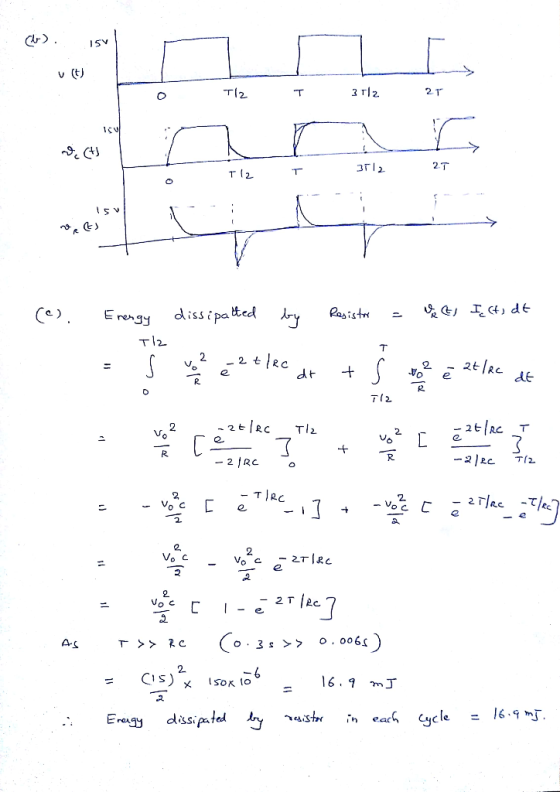
 12. A series RC circuit is driven by a periodic square wave voltage V(t) with a period T=0.3 sec. V(t) 0 for t<0. After t=0, the voltage alternates between 15 V and 0 V. Assume that R-40 , C 150 HF. We will call the voltage across the capacitor and the resistor Ve(t) and Vr(t) respectively (c) The capacitor above is now replaced by an inductor whose inductance is 0.24 H. We call the voltage across the inductor VL(t) Calculate...
1. In a series RC circuit, Vn and Vc are measured as a function of frequency....
 1. In a series RC circuit, Vn and Vc are measured as a function of frequency. Do you expect Ve and Ve to increase, decrease, or remain constant as you change f? Show your predictions by making a sketch of VR and Vc versus f 2. In a series RC circuit, the voltages across R and C are given as a function of time belo. 15 10 -5 -10 -15 0 0.01 0.02 0.03 0.04 0.05 t (sec) Sketch, on...
2π Pulse wave: o-T fb) f-32 20 Consider the series RC circuit with R- 1 kn,C1.5...
 2π Pulse wave: o-T fb) f-32 20 Consider the series RC circuit with R- 1 kn,C1.5 mF (RC-1.5 sec). The source voltage vs (t) is the Pulse Wave with A-10V T 10 sec; d-sec Use Differential Equation and/or Laplace Transform methods to analyze the operation of the circuit subject to this input. The output of interest is vc(t) It may be assumed that vc(0)0 Then, use Fourier Series methods to find vc(t) Plot and compare the results obtained using the...
16.2 Find the Fourier series expressions for the periodic voltage functions shown in Fig. P16.2. ...
 16.2 Find the Fourier series expressions for the periodic voltage functions shown in Fig. P16.2. Note that Fig. P16.2(a) illustrates the square wave; Fig. P16.2(b) illustrates the full-wave rectified sine wave, where u(t)-Yn sin(π/T), 0 t s T; and Fig. P16.2(c) illustrates the half-wave rectified sine wave, where Figure P16.2 v(t) 2T 3T rt v(0) 2T 3T v(t) nt T/2 T 3T/2
16.2 Find the Fourier series expressions for the periodic voltage functions shown in Fig. P16.2. Note that Fig....
16.2 Find the Fourier series expressions for the periodic voltage functions shown in Fig. P16.2. Note that Fig. P16.2(a) illustrates the square wave; Fig. P16.2(b) illustrates the full-wave rectified sine wave, where u(t)-Yn sin(π/T), 0 t s T; and Fig. P16.2(c) illustrates the half-wave rectified sine wave, where Figure P16.2 v(t) 2T 3T rt v(0) 2T 3T v(t) nt T/2 T 3T/2
16.2 Find the Fourier series expressions for the periodic voltage functions shown in Fig. P16.2. Note that Fig....
Determine the Fourier series expressions for the periodic voltage functions for the full wave rectified sine...
 Determine the Fourier series expressions for the periodic voltage functions for the full wave rectified sine wave shown in Figure b and the half wave rectified sine wave shown in Figure c. v(t) 0 2T 3T -T
Page 3 of 3 (5) The periodic square-wave voltage seen in Fig. 5a is applied to...
 Page 3 of 3 (5) The periodic square-wave voltage seen in Fig. 5a is applied to the circuit shown in Fig. 5b. (a) Determine the Fourier series of the periodic square-wave in Fig.5a. (b) Derive the steady-state voltage voC) as a response to the first two nonzero terms in the Fourier series that represents the v,) (20 points) v(t) 10% H 102 0 123 t (sec) -2 1 Fig. 5a Fig. 5b
The source is connected across a series RC ac circuit with R = 9 Ohm and...
 The source is connected across a series RC ac circuit with R = 9
Ohm and XC = 1/ωC = 2.7 Ohm.
Q3. The source is connected across a series RC ac circuit with R = 9 Ohm and Xc = 1/(C = 2.7 Ohm. 3a) Find the magnitude of impedance of the series combination (Unit: Ohm) Submit Answer Tries 0/3 3b) Find the phase angle of impedance of theseries combination (Unit: deg) Submit Answer Tries 0/3 3c) Calculate the...
The source is connected across a series RC ac circuit with R = 9
Ohm and XC = 1/ωC = 2.7 Ohm.
Q3. The source is connected across a series RC ac circuit with R = 9 Ohm and Xc = 1/(C = 2.7 Ohm. 3a) Find the magnitude of impedance of the series combination (Unit: Ohm) Submit Answer Tries 0/3 3b) Find the phase angle of impedance of theseries combination (Unit: deg) Submit Answer Tries 0/3 3c) Calculate the...
Consider the RC circuit in the figure below. The switch was at position a for a long period of time and it is suddenly...
 Consider the RC circuit in the figure below. The switch was at
position a for a long period of time and it is
suddenly switched to position b at time t =
0.For
each statement select True or False.1. The current through the resistor equals the current across the
capacitor at all times.2. In the instant after the switch is thrown the current across the
capacitor is zero.3. In the instant after the switch is thrown the voltage across the...
Consider the RC circuit in the figure below. The switch was at
position a for a long period of time and it is
suddenly switched to position b at time t =
0.For
each statement select True or False.1. The current through the resistor equals the current across the
capacitor at all times.2. In the instant after the switch is thrown the current across the
capacitor is zero.3. In the instant after the switch is thrown the voltage across the...
Q1: Consider the RC circuit shown below, which is being driven by a function generator supplying...
 Q1: Consider the RC circuit shown below, which is being driven by a function generator supplying a voltage of Vin(t), as shown in the figure next to the circuit Sketch the voltage that would be measured across the 10 microfarad capacitor. Assume that the period of the input square wave is several times longer than the time constant RC. 1 k 2 A voltage KAW function generator 10 MF time
1. A sawtooth wave with a period of 200ms is applied to an oscilloscope with a screen 25cm wide. What time is...
 1. A sawtooth wave with a period of 200ms is applied to an oscilloscope with a screen 25cm wide. What time is represented by 1 cm on the screen? Show your work 2. If a series RC circuit has VR = 14.5V and Vc = 9.2 V, the generator voltage must be (a) 17.2 V (b) 16.9 V (c) 4.7 V (d) 16.5 V. Show your work.
 12. A series RC circuit is driven by a periodic square wave voltage V(t) with a period T=0.3 sec. V(t) 0 for t<0. After t=0, the voltage alternates between 15 V and 0 V. Assume that R-40 , C 150 HF. We will call the voltage across the capacitor and the resistor Ve(t) and Vr(t) respectively (c) The capacitor above is now replaced by an inductor whose inductance is 0.24 H. We call the voltage across the inductor VL(t) Calculate...
 1. In a series RC circuit, Vn and Vc are measured as a function of frequency. Do you expect Ve and Ve to increase, decrease, or remain constant as you change f? Show your predictions by making a sketch of VR and Vc versus f 2. In a series RC circuit, the voltages across R and C are given as a function of time belo. 15 10 -5 -10 -15 0 0.01 0.02 0.03 0.04 0.05 t (sec) Sketch, on...
 2π Pulse wave: o-T fb) f-32 20 Consider the series RC circuit with R- 1 kn,C1.5 mF (RC-1.5 sec). The source voltage vs (t) is the Pulse Wave with A-10V T 10 sec; d-sec Use Differential Equation and/or Laplace Transform methods to analyze the operation of the circuit subject to this input. The output of interest is vc(t) It may be assumed that vc(0)0 Then, use Fourier Series methods to find vc(t) Plot and compare the results obtained using the...
 16.2 Find the Fourier series expressions for the periodic voltage functions shown in Fig. P16.2. Note that Fig. P16.2(a) illustrates the square wave; Fig. P16.2(b) illustrates the full-wave rectified sine wave, where u(t)-Yn sin(π/T), 0 t s T; and Fig. P16.2(c) illustrates the half-wave rectified sine wave, where Figure P16.2 v(t) 2T 3T rt v(0) 2T 3T v(t) nt T/2 T 3T/2
16.2 Find the Fourier series expressions for the periodic voltage functions shown in Fig. P16.2. Note that Fig....
16.2 Find the Fourier series expressions for the periodic voltage functions shown in Fig. P16.2. Note that Fig. P16.2(a) illustrates the square wave; Fig. P16.2(b) illustrates the full-wave rectified sine wave, where u(t)-Yn sin(π/T), 0 t s T; and Fig. P16.2(c) illustrates the half-wave rectified sine wave, where Figure P16.2 v(t) 2T 3T rt v(0) 2T 3T v(t) nt T/2 T 3T/2
16.2 Find the Fourier series expressions for the periodic voltage functions shown in Fig. P16.2. Note that Fig....
 Determine the Fourier series expressions for the periodic voltage functions for the full wave rectified sine wave shown in Figure b and the half wave rectified sine wave shown in Figure c. v(t) 0 2T 3T -T
 Page 3 of 3 (5) The periodic square-wave voltage seen in Fig. 5a is applied to the circuit shown in Fig. 5b. (a) Determine the Fourier series of the periodic square-wave in Fig.5a. (b) Derive the steady-state voltage voC) as a response to the first two nonzero terms in the Fourier series that represents the v,) (20 points) v(t) 10% H 102 0 123 t (sec) -2 1 Fig. 5a Fig. 5b
 The source is connected across a series RC ac circuit with R = 9
Ohm and XC = 1/ωC = 2.7 Ohm.
Q3. The source is connected across a series RC ac circuit with R = 9 Ohm and Xc = 1/(C = 2.7 Ohm. 3a) Find the magnitude of impedance of the series combination (Unit: Ohm) Submit Answer Tries 0/3 3b) Find the phase angle of impedance of theseries combination (Unit: deg) Submit Answer Tries 0/3 3c) Calculate the...
The source is connected across a series RC ac circuit with R = 9
Ohm and XC = 1/ωC = 2.7 Ohm.
Q3. The source is connected across a series RC ac circuit with R = 9 Ohm and Xc = 1/(C = 2.7 Ohm. 3a) Find the magnitude of impedance of the series combination (Unit: Ohm) Submit Answer Tries 0/3 3b) Find the phase angle of impedance of theseries combination (Unit: deg) Submit Answer Tries 0/3 3c) Calculate the...
 Consider the RC circuit in the figure below. The switch was at
position a for a long period of time and it is
suddenly switched to position b at time t =
0.For
each statement select True or False.1. The current through the resistor equals the current across the
capacitor at all times.2. In the instant after the switch is thrown the current across the
capacitor is zero.3. In the instant after the switch is thrown the voltage across the...
Consider the RC circuit in the figure below. The switch was at
position a for a long period of time and it is
suddenly switched to position b at time t =
0.For
each statement select True or False.1. The current through the resistor equals the current across the
capacitor at all times.2. In the instant after the switch is thrown the current across the
capacitor is zero.3. In the instant after the switch is thrown the voltage across the...
 Q1: Consider the RC circuit shown below, which is being driven by a function generator supplying a voltage of Vin(t), as shown in the figure next to the circuit Sketch the voltage that would be measured across the 10 microfarad capacitor. Assume that the period of the input square wave is several times longer than the time constant RC. 1 k 2 A voltage KAW function generator 10 MF time
 1. A sawtooth wave with a period of 200ms is applied to an oscilloscope with a screen 25cm wide. What time is represented by 1 cm on the screen? Show your work 2. If a series RC circuit has VR = 14.5V and Vc = 9.2 V, the generator voltage must be (a) 17.2 V (b) 16.9 V (c) 4.7 V (d) 16.5 V. Show your work.
Most questions answered within 3 hours.
-
The average length of time between arrivals at a turnpike
toll-booth is 26 seconds. What is...
asked 46 minutes ago -
(a) A piston at 6.1 atm contains a gas that occupies a volume of
3.5 L....
asked 1 hour ago -
Please answer true or false. Words
cannot be changed or added in to make it true...
asked 1 hour ago -
An empty test tube weighs 15.923 grams. Then,
MgCl2•6H2O is added into the test tube. After...
asked 2 hours ago -
Assume memory access is 10 units of time and disk access is
10000 units of time....
asked 2 hours ago -
1. Are all good samples random?
2. Magazines often report surveys giving statistics such as “63%...
asked 2 hours ago -
Under all the various types of market structures, firms
must eventually earn some economic profits for...
asked 2 hours ago -
Consider the following fitness regime for a single locus trait
with two co-dominant alleles: w11 =...
asked 2 hours ago -
A large cable company reports the following.
80% of its customers subscribe to its cable TV...
asked 2 hours ago -
Please answer the question in brief.
Discuss the role of ERP in organizations. Are ERP tools...
asked 2 hours ago -
Discuss the pros and cons of collaborative software such
as SameTime. Does it increase productivity? What...
asked 2 hours ago -
Buying your in-laws a gift because it’s expected is
due to the ____________ motive of gift-giving....
asked 2 hours ago