

Homework Answers


Add Answer to:
12. A series RC circuit is driven by a periodic square wave voltage V(t) with a period T=0.3 sec. V(t) 0 for t<0. A...
12. A series RC circuit is driven by a periodic square wave voltage V(t) with a period T=0.3 sec. V(t)0 for t<0. Aft...
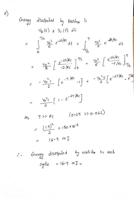
 12. A series RC circuit is driven by a periodic square wave voltage V(t) with a period T=0.3 sec. V(t)0 for t<0. After t=0, the voltage alternates between 15 V and 0 V. Assume that R-40 , C-150 HF. We will call the voltage across the capacitor and the resistor Ve(t and Vr(t) respectively (a) Calculate the current I(t) in the circuit, the voltage Vc(t), and the power delivered by the driving source as a function of time for the...
A series LRC circuit is driven by an alternating source with rms voltage 700 V and...
A series LRC circuit is driven by an alternating source with rms voltage 700 V and angular frequency 500 rad/s. The circuit elements are a 400 Ω resistor, a 4.0 μF capacitor and a 0.40 H inductor. If the resistor and inductor are side by side, what would be the rms voltage across the two elements?
Series and parallel RL and RC circuits with an AC source. A 60 Hz voltage source...
 Series and parallel RL and RC circuits with an AC source. A 60 Hz voltage source has an amplitude of VT-120 V. For the following problems, compute the indicated phasors including both magnitudes and phase angles, and sketch the phasor diagrams (no submission) Q1. The source is connected across a series RL ac circuit with R 7.8 Ohm and XL = ωし= 5.1 Ohm. 1a) Find the magnitude of impedance of the series combination (Unit: Ohm) Submit Answer Tries 0/3...
A series LRC circuit is driven by an ac source with a voltage amplitude of 36.0...
 A series LRC circuit is driven by an ac source with a voltage amplitude of 36.0 V and a frequency of 60.0 Hz. The resistance is 160 Ohm, the inductance is 0.230 H, and the capacitance is 70.0 mu F. a) Determine the impedance of the circuit. b) Determine the current amplitude. c) Determine the voltage amplitude across (i) the resistor, (ii) the inductor and (iii) the capacitor. d) Sketch the phasor diagram (at t = 0) for the circuit,...
The source is connected across a series RC ac circuit with R = 9 Ohm and...
 The source is connected across a series RC ac circuit with R = 9
Ohm and XC = 1/ωC = 2.7 Ohm.
Q3. The source is connected across a series RC ac circuit with R = 9 Ohm and Xc = 1/(C = 2.7 Ohm. 3a) Find the magnitude of impedance of the series combination (Unit: Ohm) Submit Answer Tries 0/3 3b) Find the phase angle of impedance of theseries combination (Unit: deg) Submit Answer Tries 0/3 3c) Calculate the...
The source is connected across a series RC ac circuit with R = 9
Ohm and XC = 1/ωC = 2.7 Ohm.
Q3. The source is connected across a series RC ac circuit with R = 9 Ohm and Xc = 1/(C = 2.7 Ohm. 3a) Find the magnitude of impedance of the series combination (Unit: Ohm) Submit Answer Tries 0/3 3b) Find the phase angle of impedance of theseries combination (Unit: deg) Submit Answer Tries 0/3 3c) Calculate the...
an RC circuit has capacitor C=1, Resistor R=0.5, and voltage source x(t) all in series. With...
an RC circuit has capacitor C=1, Resistor R=0.5, and voltage source x(t) all in series. With zero initial condition, and x(t)=u(t), what is voltage across capacitor, y(t)?
Tylors Series Solve by using the second Order Taylors Series Method. Assume step size h=0.3 Consider...
 Tylors Series
Solve by using the second Order Taylors Series Method. Assume step size h=0.3 Consider the RC circuit which is shown in the figure below. The charge Q across the capacitor at time to sec is o Coulomb, which is Q(0)=0 Coulomb, Given that C=2 F, R=12, and Vpc =5 V. The switch is closed at time t=0 sec, and the differential equation concerning the circuit is given as 99-1 -Q+ CV ).where Q is the charge stored in...
Tylors Series
Solve by using the second Order Taylors Series Method. Assume step size h=0.3 Consider the RC circuit which is shown in the figure below. The charge Q across the capacitor at time to sec is o Coulomb, which is Q(0)=0 Coulomb, Given that C=2 F, R=12, and Vpc =5 V. The switch is closed at time t=0 sec, and the differential equation concerning the circuit is given as 99-1 -Q+ CV ).where Q is the charge stored in...
Q1: Consider the RC circuit shown below, which is being driven by a function generator supplying...
 Q1: Consider the RC circuit shown below, which is being driven by a function generator supplying a voltage of Vin(t), as shown in the figure next to the circuit Sketch the voltage that would be measured across the 10 microfarad capacitor. Assume that the period of the input square wave is several times longer than the time constant RC. 1 k 2 A voltage KAW function generator 10 MF time
A series RC circuit has resistance R - 14.00 inductive reactance X20:00, and capacitive reactance X...
 A series RC circuit has resistance R - 14.00 inductive reactance X20:00, and capacitive reactance X 12. 00. If the maximum voltage across the resistor is av = 125 V, find the maximum voltage across the inductor and the capacitor. (Due to the nature of this problem, do not use rounded intermediate values in your calculations including answers submitted in Webassin) HINT (a) the maximum voltage across the inductor (in V) (b) the maximum voltage across the capacitor ( V)...
Page 3 of 3 (5) The periodic square-wave voltage seen in Fig. 5a is applied to...
 Page 3 of 3 (5) The periodic square-wave voltage seen in Fig. 5a is applied to the circuit shown in Fig. 5b. (a) Determine the Fourier series of the periodic square-wave in Fig.5a. (b) Derive the steady-state voltage voC) as a response to the first two nonzero terms in the Fourier series that represents the v,) (20 points) v(t) 10% H 102 0 123 t (sec) -2 1 Fig. 5a Fig. 5b
 12. A series RC circuit is driven by a periodic square wave voltage V(t) with a period T=0.3 sec. V(t)0 for t<0. After t=0, the voltage alternates between 15 V and 0 V. Assume that R-40 , C-150 HF. We will call the voltage across the capacitor and the resistor Ve(t and Vr(t) respectively (a) Calculate the current I(t) in the circuit, the voltage Vc(t), and the power delivered by the driving source as a function of time for the...
 Series and parallel RL and RC circuits with an AC source. A 60 Hz voltage source has an amplitude of VT-120 V. For the following problems, compute the indicated phasors including both magnitudes and phase angles, and sketch the phasor diagrams (no submission) Q1. The source is connected across a series RL ac circuit with R 7.8 Ohm and XL = ωし= 5.1 Ohm. 1a) Find the magnitude of impedance of the series combination (Unit: Ohm) Submit Answer Tries 0/3...
 A series LRC circuit is driven by an ac source with a voltage amplitude of 36.0 V and a frequency of 60.0 Hz. The resistance is 160 Ohm, the inductance is 0.230 H, and the capacitance is 70.0 mu F. a) Determine the impedance of the circuit. b) Determine the current amplitude. c) Determine the voltage amplitude across (i) the resistor, (ii) the inductor and (iii) the capacitor. d) Sketch the phasor diagram (at t = 0) for the circuit,...
 The source is connected across a series RC ac circuit with R = 9
Ohm and XC = 1/ωC = 2.7 Ohm.
Q3. The source is connected across a series RC ac circuit with R = 9 Ohm and Xc = 1/(C = 2.7 Ohm. 3a) Find the magnitude of impedance of the series combination (Unit: Ohm) Submit Answer Tries 0/3 3b) Find the phase angle of impedance of theseries combination (Unit: deg) Submit Answer Tries 0/3 3c) Calculate the...
The source is connected across a series RC ac circuit with R = 9
Ohm and XC = 1/ωC = 2.7 Ohm.
Q3. The source is connected across a series RC ac circuit with R = 9 Ohm and Xc = 1/(C = 2.7 Ohm. 3a) Find the magnitude of impedance of the series combination (Unit: Ohm) Submit Answer Tries 0/3 3b) Find the phase angle of impedance of theseries combination (Unit: deg) Submit Answer Tries 0/3 3c) Calculate the...
 Tylors Series
Solve by using the second Order Taylors Series Method. Assume step size h=0.3 Consider the RC circuit which is shown in the figure below. The charge Q across the capacitor at time to sec is o Coulomb, which is Q(0)=0 Coulomb, Given that C=2 F, R=12, and Vpc =5 V. The switch is closed at time t=0 sec, and the differential equation concerning the circuit is given as 99-1 -Q+ CV ).where Q is the charge stored in...
Tylors Series
Solve by using the second Order Taylors Series Method. Assume step size h=0.3 Consider the RC circuit which is shown in the figure below. The charge Q across the capacitor at time to sec is o Coulomb, which is Q(0)=0 Coulomb, Given that C=2 F, R=12, and Vpc =5 V. The switch is closed at time t=0 sec, and the differential equation concerning the circuit is given as 99-1 -Q+ CV ).where Q is the charge stored in...
 Q1: Consider the RC circuit shown below, which is being driven by a function generator supplying a voltage of Vin(t), as shown in the figure next to the circuit Sketch the voltage that would be measured across the 10 microfarad capacitor. Assume that the period of the input square wave is several times longer than the time constant RC. 1 k 2 A voltage KAW function generator 10 MF time
 A series RC circuit has resistance R - 14.00 inductive reactance X20:00, and capacitive reactance X 12. 00. If the maximum voltage across the resistor is av = 125 V, find the maximum voltage across the inductor and the capacitor. (Due to the nature of this problem, do not use rounded intermediate values in your calculations including answers submitted in Webassin) HINT (a) the maximum voltage across the inductor (in V) (b) the maximum voltage across the capacitor ( V)...
 Page 3 of 3 (5) The periodic square-wave voltage seen in Fig. 5a is applied to the circuit shown in Fig. 5b. (a) Determine the Fourier series of the periodic square-wave in Fig.5a. (b) Derive the steady-state voltage voC) as a response to the first two nonzero terms in the Fourier series that represents the v,) (20 points) v(t) 10% H 102 0 123 t (sec) -2 1 Fig. 5a Fig. 5b
Most questions answered within 3 hours.
-
Calculate the pH of a 5.7 M solution of aniline (C6H5NH2; Kb =
3.8 x 10^-10)
asked 23 minutes ago -
LSL R3, R3, R12
Memory
Address
Orig.
Data
Updated
Data
Register
Orig.
Data
Updated
Data
0x84F0...
asked 25 minutes ago -
Air at 100 kPa and density of 1.2 kg/m3 flows upward through a
5-cm diameter inclined...
asked 33 minutes ago -
Define the following concepts in your own words: (a) stiffness,
(b) strength, (c) strain,
(d) ductility,...
asked 1 hour ago -
In C++
In this homework, you will be tasked with creating functions to
manipulate strings that...
asked 1 hour ago -
An isolated colony represents a pure culture. one rare occasions
, however , a colony can...
asked 2 hours ago -
*****DO NOT ANSWER THIS QUESTION IF YOU DON'T
KNOW*******Rights and Duties of Auditors; Minimum 4000
words...
asked 3 hours ago -
The probability that Janie is wearing sunglasses is 1/4. The
probability that she is wearing sunglasses...
asked 3 hours ago -
Do you believe social media is more of a help or a hindrance in
controlling crises...
asked 3 hours ago -
Two long, parallel wires separated by 2.85 cm carry currents in
opposite directions. The current in...
asked 3 hours ago -
Question # 1. Develop a list of rehabilitation journals
that publish articles concerning career counseling for...
asked 3 hours ago -
Bryant Company has a factory machine with a book value of
$85,100 and a remaining useful...
asked 3 hours ago