
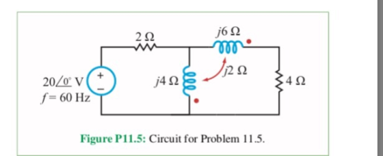
2Ω j6Ω /4Ω 4Ω f-60 Hz Figure P11.5: Circuit for Problem 11.5
Homework Answers
Add Answer to:
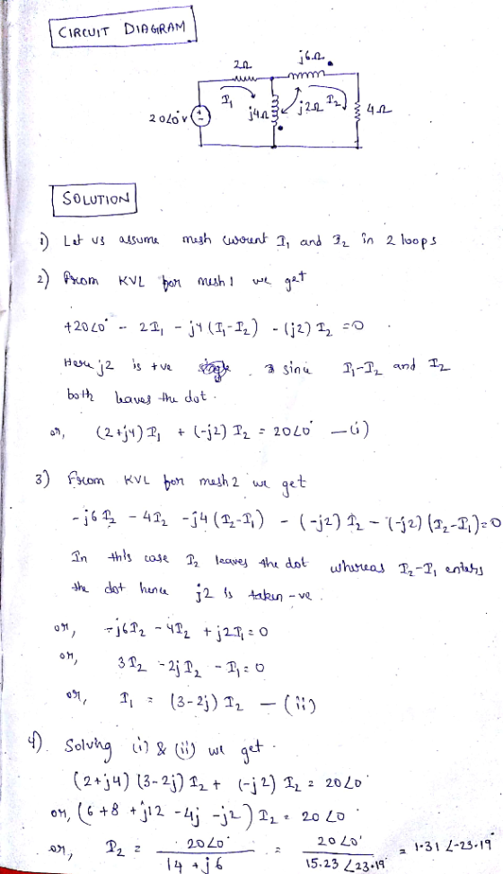
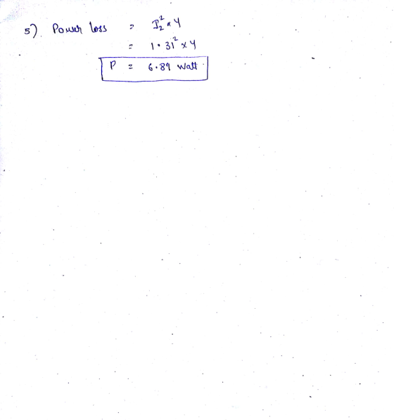
11.5 Determine the average power dissipated in the 4Ω resistor of the circuit in Fig. P11.5 2Ω ...
Find I, in the circuit of Fig. 2. 4Ω Ι, 22 2Ο | -2Ω j6Ω 60/30°...
 Find I, in the circuit of Fig. 2. 4Ω Ι, 22 2Ο | -2Ω j6Ω 60/30° V (4) ξ8 Ω 3 10 Ω Figure 2
Determine the current and the power dissipated throughout the circuit using nodal analysis and mesh analysis....
 Determine the current and the power dissipated throughout the
circuit using nodal analysis and mesh analysis.
30 ν 2Ω 2Ω 4Ω 15А 8Ω
Determine the current and the power dissipated throughout the
circuit using nodal analysis and mesh analysis.
30 ν 2Ω 2Ω 4Ω 15А 8Ω
The variable resistor (R0) in the circuit is adjusted until the power the power dissipated in...
 The variable resistor (R0) in the circuit is adjusted until the
power the power dissipated in the resistor is 250W. Find the values
of R0 that satisfy this condistion.
4.87 The variable resistor (Ro) in the circuit in Fig. P4.87 PPIis adjusted until the power dissipated in the resistor is 250 W. Find the values of Ro that satisfy this con- MULTISIM dition. Figure P4.87 25 Ω 10 Ω 200 V 100 Ro 30
The variable resistor (R0) in the circuit is adjusted until the
power the power dissipated in the resistor is 250W. Find the values
of R0 that satisfy this condistion.
4.87 The variable resistor (Ro) in the circuit in Fig. P4.87 PPIis adjusted until the power dissipated in the resistor is 250 W. Find the values of Ro that satisfy this con- MULTISIM dition. Figure P4.87 25 Ω 10 Ω 200 V 100 Ro 30
Find the power dissipated by the 2Ω resistor ISV find the power dist paled by the...
 Find the
power dissipated by the 2Ω resistor
ISV find the power dist paled by the 2.2 re 6tor
Find the
power dissipated by the 2Ω resistor
ISV find the power dist paled by the 2.2 re 6tor
3. For the circuit given, determine the average power dissipated in the 100 KA2 resistor. (5...
 3. For the circuit given, determine the average power dissipated in the 100 KA2 resistor. (5 pts) 100 Ω 1 : 10 50 Vrms 8 100 ΚΩ
Problem 10.14 please 2Ω Figure P10.15 Figure P10.13 10.14 Find I, in the circuit in Fig....
 Problem 10.14 please
2Ω Figure P10.15 Figure P10.13 10.14 Find I, in the circuit in Fig. P10.14. 12Ω 4Ω 4Ω 6/0V Io Figure P10.14
Problem 10.14 please
2Ω Figure P10.15 Figure P10.13 10.14 Find I, in the circuit in Fig. P10.14. 12Ω 4Ω 4Ω 6/0V Io Figure P10.14
Consider the circuit below, solve for average power dissipated in the capacitor and resistor for capacitor...
 Consider the circuit below, solve for average power dissipated in the capacitor and resistor for capacitor impedance -;12, -3212, and -j312. Plot the power dissipated in the resistor over the capacitor impedance. 120 R 122
Answer # 3,27 PROBLEMS 3.27 Use mesh analysis to determine the amount of power supplied by...
 Answer # 3,27
PROBLEMS 3.27 Use mesh analysis to determine the amount of power supplied by the voltage source in the circuit of Fig. P3.27. 8Ω 9 A 2Ω 4Ω +40 V Figure P3.27: Circuit for Problem 3.27. 28 Determine V in the circuit of Fig. P3.28 using mesh alysis 4Ω 4Ω
Answer # 3,27
PROBLEMS 3.27 Use mesh analysis to determine the amount of power supplied by the voltage source in the circuit of Fig. P3.27. 8Ω 9 A 2Ω 4Ω +40 V Figure P3.27: Circuit for Problem 3.27. 28 Determine V in the circuit of Fig. P3.28 using mesh alysis 4Ω 4Ω
ters for circun 4Ω -/1012 : 12 Ω j6Ω Vnd y arameter für ereuit shown in...
 ters for circun 4Ω -/1012 : 12 Ω j6Ω Vnd y arameter für ereuit shown in figures Fig. 3 Fig. 2 shown t reuit parameter for circuit shown in figure 4. gure 5 3i 10 4, 2Ω 20 Ω 612 4Ω Fig. 5 Fig. 4 and Yn= Find out the network for which the Y parameter areXi--,y12=ー, Y21 6. 7. Determine the hybrid parameter for the circuit shown in figure-6 8. Find Vi and V2 in figure 7 25 Ω...
Determine Vx in the circuit of Figure 3. 4Ω 2/ 2Ω 6Ω ΙΩ +8 V 1Ω...
 Determine Vx in the circuit of Figure 3. 4Ω 2/ 2Ω 6Ω ΙΩ +8 V 1Ω Figure 3
 Find I, in the circuit of Fig. 2. 4Ω Ι, 22 2Ο | -2Ω j6Ω 60/30° V (4) ξ8 Ω 3 10 Ω Figure 2
 Determine the current and the power dissipated throughout the
circuit using nodal analysis and mesh analysis.
30 ν 2Ω 2Ω 4Ω 15А 8Ω
Determine the current and the power dissipated throughout the
circuit using nodal analysis and mesh analysis.
30 ν 2Ω 2Ω 4Ω 15А 8Ω
 The variable resistor (R0) in the circuit is adjusted until the
power the power dissipated in the resistor is 250W. Find the values
of R0 that satisfy this condistion.
4.87 The variable resistor (Ro) in the circuit in Fig. P4.87 PPIis adjusted until the power dissipated in the resistor is 250 W. Find the values of Ro that satisfy this con- MULTISIM dition. Figure P4.87 25 Ω 10 Ω 200 V 100 Ro 30
The variable resistor (R0) in the circuit is adjusted until the
power the power dissipated in the resistor is 250W. Find the values
of R0 that satisfy this condistion.
4.87 The variable resistor (Ro) in the circuit in Fig. P4.87 PPIis adjusted until the power dissipated in the resistor is 250 W. Find the values of Ro that satisfy this con- MULTISIM dition. Figure P4.87 25 Ω 10 Ω 200 V 100 Ro 30
 Find the
power dissipated by the 2Ω resistor
ISV find the power dist paled by the 2.2 re 6tor
Find the
power dissipated by the 2Ω resistor
ISV find the power dist paled by the 2.2 re 6tor
 3. For the circuit given, determine the average power dissipated in the 100 KA2 resistor. (5 pts) 100 Ω 1 : 10 50 Vrms 8 100 ΚΩ
 Problem 10.14 please
2Ω Figure P10.15 Figure P10.13 10.14 Find I, in the circuit in Fig. P10.14. 12Ω 4Ω 4Ω 6/0V Io Figure P10.14
Problem 10.14 please
2Ω Figure P10.15 Figure P10.13 10.14 Find I, in the circuit in Fig. P10.14. 12Ω 4Ω 4Ω 6/0V Io Figure P10.14
 Consider the circuit below, solve for average power dissipated in the capacitor and resistor for capacitor impedance -;12, -3212, and -j312. Plot the power dissipated in the resistor over the capacitor impedance. 120 R 122
 Answer # 3,27
PROBLEMS 3.27 Use mesh analysis to determine the amount of power supplied by the voltage source in the circuit of Fig. P3.27. 8Ω 9 A 2Ω 4Ω +40 V Figure P3.27: Circuit for Problem 3.27. 28 Determine V in the circuit of Fig. P3.28 using mesh alysis 4Ω 4Ω
Answer # 3,27
PROBLEMS 3.27 Use mesh analysis to determine the amount of power supplied by the voltage source in the circuit of Fig. P3.27. 8Ω 9 A 2Ω 4Ω +40 V Figure P3.27: Circuit for Problem 3.27. 28 Determine V in the circuit of Fig. P3.28 using mesh alysis 4Ω 4Ω
 ters for circun 4Ω -/1012 : 12 Ω j6Ω Vnd y arameter für ereuit shown in figures Fig. 3 Fig. 2 shown t reuit parameter for circuit shown in figure 4. gure 5 3i 10 4, 2Ω 20 Ω 612 4Ω Fig. 5 Fig. 4 and Yn= Find out the network for which the Y parameter areXi--,y12=ー, Y21 6. 7. Determine the hybrid parameter for the circuit shown in figure-6 8. Find Vi and V2 in figure 7 25 Ω...
 Determine Vx in the circuit of Figure 3. 4Ω 2/ 2Ω 6Ω ΙΩ +8 V 1Ω Figure 3
Most questions answered within 3 hours.
-
(63
#14)
which of the following statments best describes how chamging
the concentration of the substances...
asked 2 hours ago -
In the following reaction, which element is undergoing
oxidation: Na2SO3 + N2O --> N2 + Na2SO4...
asked 3 hours ago -
Which of the following pairs of ions have the same electron
configuration?
I: Br− and Se2−...
asked 6 hours ago -
The Foremost Composite Materials Company is planning a two-day
sales conference for October 19-20. The conference...
asked 6 hours ago -
3) Illustrate the observed pattern of relatedness of organisms
versus adaptations to specific conditions. This means...
asked 6 hours ago -
In winter a lake has a 0.35 m thick ice layer over 1.10 m of
water....
asked 7 hours ago -
Assuming the following has been encrypted with a Vigenere cipher
below, use the method(s) and assumptions...
asked 8 hours ago -
How would I use switch statements to write a program that will
take an input of...
asked 8 hours ago -
Imagine a reaction in which methane gas combusts at a constant
pressure of 1 atm and...
asked 8 hours ago -
Two parallel wires (each 12 m in length) are separated by a
distance of 0.065 m...
asked 8 hours ago -
Suppose there were three masses at the corner of uniform
equilateral triangle. The masses are m1...
asked 8 hours ago -
Situation: A building that is 618 m above the ground floor. How
many times would a...
asked 8 hours ago