
Homework Answers


The simulations are given as follows
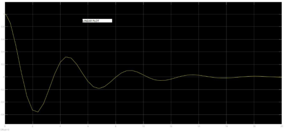
Nonlinear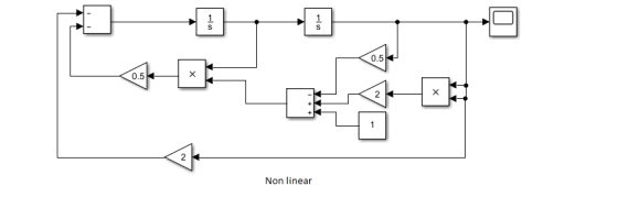
Non linear plot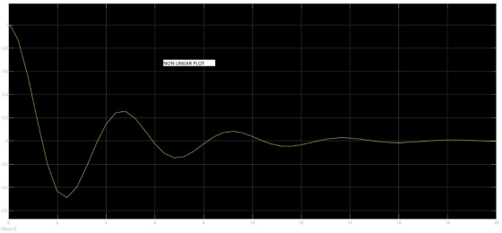
Linear 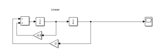
Linear plot
Linear and non linear plot comparison
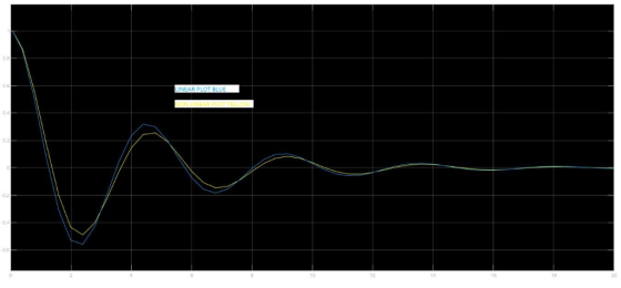
Difference at 4 sec is 0.8.
Add Answer to:
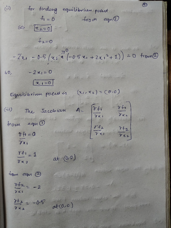
A colleague gave you a Simulink model (figure 5) for a non-linear mass-spring-damper system but f...
Question8 n the spring-mass-damper system in Figure 8, the force F, is applied to the mass and it...
 Question8 n the spring-mass-damper system in Figure 8, the force F, is applied to the mass and its displacement is measured via r(t), whilst k and c are the spring and damper constants, respectively x(t) Figure 8: A spring-mass-damper system. a) Obtain the differential equation that relates the input force F, to the measured dis- (6 marks) placement x(t) for the system in Figure 8. b) Draw the block diagram representation of the system in Figure 8. c) Based on...
Problem 1. Consider the following mass, spring, and damper system. Let the force F be the...
 Problem 1. Consider the following mass, spring, and damper system. Let the force F be the input and the position x be the output. M-1 kg b- 10 N s/m k 20 N/nm F = 1 N when t>=0 PART UNIT FEEDBACK CONTROL SYSTEM 5) Construct a unit feedback control for the mass-spring-damper system 6) Draw the block diagram of the unit feedback control system 7) Find the Transfer Function of the closed-loop (CL) system 8) Find and plot the...
Consider the following second-order ODE representing a spring-mass-damper system for zero initial...
 Consider the following second-order ODE representing a spring-mass-damper system for zero initial conditions (forced response): where u is the Unit Step Function (of magnitude 1 a. Use MATLAB to obtain an analytical solution x() for the differential equation, using the Laplace Transforms approach (do not use DSOLVE). Obtain the analytical expression for ao. Also obtain a plot of x() (for a simulation of 14 seconds) b. Obtain the Transfer Function representation for the system. c. Use MATLAB to obtain the...
Please write legibly Consider an ideal mass-spring-damper system similar to Figure 3.2. Find the damping coefficient of the system if a mass of 380 g is used in combination with a spring with stif...
 Please write legibly
Consider an ideal mass-spring-damper system similar to Figure 3.2. Find the damping coefficient of the system if a mass of 380 g is used in combination with a spring with stiffness k = 17 N/m and a period of 0.945 s. If the system is released from rest 5 cm from it's equilibrium point at to = 0 s, find the trajectory of the position of the mass-spring-damper from it's release until t 3s Figure 3.2: Mass-spring-damper...
Please write legibly
Consider an ideal mass-spring-damper system similar to Figure 3.2. Find the damping coefficient of the system if a mass of 380 g is used in combination with a spring with stiffness k = 17 N/m and a period of 0.945 s. If the system is released from rest 5 cm from it's equilibrium point at to = 0 s, find the trajectory of the position of the mass-spring-damper from it's release until t 3s Figure 3.2: Mass-spring-damper...
5. Consider the model of a spring-mass-damper system, where the following parameter values are as...
 5. Consider the model of a spring-mass-damper system, where the following parameter values are assumed: m 1,b 2, k 2 a. Design a rate feedback controller to meet the following step response specifictions: ts 1 s, ζ 206. b. Compare the step response of the closed-loop systems in Probs. 3&5
5. Consider the model of a spring-mass-damper system, where the following parameter values are assumed: m 1,b 2, k 2 a. Design a rate feedback controller to meet the following...
5. Consider the model of a spring-mass-damper system, where the following parameter values are assumed: m 1,b 2, k 2 a. Design a rate feedback controller to meet the following step response specifictions: ts 1 s, ζ 206. b. Compare the step response of the closed-loop systems in Probs. 3&5
5. Consider the model of a spring-mass-damper system, where the following parameter values are assumed: m 1,b 2, k 2 a. Design a rate feedback controller to meet the following...
63 Figure P6.3 shows a mass-damper system (no stiffness, Problem 2.3). Displacement x is measured...
 63 Figure P6.3 shows a mass-damper system (no stiffness, Problem 2.3). Displacement x is measured from an equilibrium position where the damper is at the "neutral" position. The external force () is a short-duration pulse function: f(!)-5N for 0SS002 s, and f,() = 0 for t > 0.02 s. The system parameters are mass m-0.5kg and viscous friction coefficient b 3 N-s/m and the system is initially at rest. Usc Simulink to determine the system response and plot displacement xit)...
Consider the mass-spring-damper system depicted in the figure below, where the input of the system is...
 Consider the mass-spring-damper system depicted in the figure below, where the input of the system is the applied force F(t) and the output of the system is xít) that is the displacement of the mass according to the coordinate system defined in that figure. Assume that force F(t) is applied for t> 0 and the system is in static equilibrium before t=0 and z(t) is measured from the static equilibrium. b m F Also, the mass of the block, the...
(By hand) Suppose a spring-mass-damper system with mass m, linear damping coefficient cand spring constant k...
 (By hand) Suppose a spring-mass-damper system with mass m, linear damping coefficient cand spring constant k is subject to a force given by Equation 1 above. Determine the steady state response of the system to the above force. f(t) = 3 1-1 - 7/2 <t<o 1 0<t</2 1
Consider the model of a spring-mass-damper system, where the following parameter values are assum...
 Consider the model of a spring-mass-damper system, where the following parameter values are assumed: m-1,b 2, k- 2. a. Write down the transfer function of the system b. Sketch a root locus for static controller gain K c. Find the range of K for stability
Consider the model of a spring-mass-damper system, where the following parameter values are assumed: m-1,b 2, k- 2. a. Write down the transfer function of the system b. Sketch a root locus for static controller...
Consider the model of a spring-mass-damper system, where the following parameter values are assumed: m-1,b 2, k- 2. a. Write down the transfer function of the system b. Sketch a root locus for static controller gain K c. Find the range of K for stability
Consider the model of a spring-mass-damper system, where the following parameter values are assumed: m-1,b 2, k- 2. a. Write down the transfer function of the system b. Sketch a root locus for static controller...
a can be skipped Consider the following second-order ODE representing a spring-mass-damper system for zero initial...
 a can be skipped
Consider the following second-order ODE representing a spring-mass-damper system for zero initial conditions (forced response): 2x + 2x + x=u, x(0) = 0, *(0) = 0 where u is the Unit Step Function (of magnitude 1). a. Use MATLAB to obtain an analytical solution x(t) for the differential equation, using the Laplace Transforms approach (do not use DSOLVE). Obtain the analytical expression for x(t). Also obtain a plot of .x(t) (for a simulation of 14 seconds)...
a can be skipped
Consider the following second-order ODE representing a spring-mass-damper system for zero initial conditions (forced response): 2x + 2x + x=u, x(0) = 0, *(0) = 0 where u is the Unit Step Function (of magnitude 1). a. Use MATLAB to obtain an analytical solution x(t) for the differential equation, using the Laplace Transforms approach (do not use DSOLVE). Obtain the analytical expression for x(t). Also obtain a plot of .x(t) (for a simulation of 14 seconds)...
 Question8 n the spring-mass-damper system in Figure 8, the force F, is applied to the mass and its displacement is measured via r(t), whilst k and c are the spring and damper constants, respectively x(t) Figure 8: A spring-mass-damper system. a) Obtain the differential equation that relates the input force F, to the measured dis- (6 marks) placement x(t) for the system in Figure 8. b) Draw the block diagram representation of the system in Figure 8. c) Based on...
 Problem 1. Consider the following mass, spring, and damper system. Let the force F be the input and the position x be the output. M-1 kg b- 10 N s/m k 20 N/nm F = 1 N when t>=0 PART UNIT FEEDBACK CONTROL SYSTEM 5) Construct a unit feedback control for the mass-spring-damper system 6) Draw the block diagram of the unit feedback control system 7) Find the Transfer Function of the closed-loop (CL) system 8) Find and plot the...
 Consider the following second-order ODE representing a spring-mass-damper system for zero initial conditions (forced response): where u is the Unit Step Function (of magnitude 1 a. Use MATLAB to obtain an analytical solution x() for the differential equation, using the Laplace Transforms approach (do not use DSOLVE). Obtain the analytical expression for ao. Also obtain a plot of x() (for a simulation of 14 seconds) b. Obtain the Transfer Function representation for the system. c. Use MATLAB to obtain the...
 Please write legibly
Consider an ideal mass-spring-damper system similar to Figure 3.2. Find the damping coefficient of the system if a mass of 380 g is used in combination with a spring with stiffness k = 17 N/m and a period of 0.945 s. If the system is released from rest 5 cm from it's equilibrium point at to = 0 s, find the trajectory of the position of the mass-spring-damper from it's release until t 3s Figure 3.2: Mass-spring-damper...
Please write legibly
Consider an ideal mass-spring-damper system similar to Figure 3.2. Find the damping coefficient of the system if a mass of 380 g is used in combination with a spring with stiffness k = 17 N/m and a period of 0.945 s. If the system is released from rest 5 cm from it's equilibrium point at to = 0 s, find the trajectory of the position of the mass-spring-damper from it's release until t 3s Figure 3.2: Mass-spring-damper...
 5. Consider the model of a spring-mass-damper system, where the following parameter values are assumed: m 1,b 2, k 2 a. Design a rate feedback controller to meet the following step response specifictions: ts 1 s, ζ 206. b. Compare the step response of the closed-loop systems in Probs. 3&5
5. Consider the model of a spring-mass-damper system, where the following parameter values are assumed: m 1,b 2, k 2 a. Design a rate feedback controller to meet the following...
5. Consider the model of a spring-mass-damper system, where the following parameter values are assumed: m 1,b 2, k 2 a. Design a rate feedback controller to meet the following step response specifictions: ts 1 s, ζ 206. b. Compare the step response of the closed-loop systems in Probs. 3&5
5. Consider the model of a spring-mass-damper system, where the following parameter values are assumed: m 1,b 2, k 2 a. Design a rate feedback controller to meet the following...
 63 Figure P6.3 shows a mass-damper system (no stiffness, Problem 2.3). Displacement x is measured from an equilibrium position where the damper is at the "neutral" position. The external force () is a short-duration pulse function: f(!)-5N for 0SS002 s, and f,() = 0 for t > 0.02 s. The system parameters are mass m-0.5kg and viscous friction coefficient b 3 N-s/m and the system is initially at rest. Usc Simulink to determine the system response and plot displacement xit)...
 Consider the mass-spring-damper system depicted in the figure below, where the input of the system is the applied force F(t) and the output of the system is xít) that is the displacement of the mass according to the coordinate system defined in that figure. Assume that force F(t) is applied for t> 0 and the system is in static equilibrium before t=0 and z(t) is measured from the static equilibrium. b m F Also, the mass of the block, the...
 (By hand) Suppose a spring-mass-damper system with mass m, linear damping coefficient cand spring constant k is subject to a force given by Equation 1 above. Determine the steady state response of the system to the above force. f(t) = 3 1-1 - 7/2 <t<o 1 0<t</2 1
 Consider the model of a spring-mass-damper system, where the following parameter values are assumed: m-1,b 2, k- 2. a. Write down the transfer function of the system b. Sketch a root locus for static controller gain K c. Find the range of K for stability
Consider the model of a spring-mass-damper system, where the following parameter values are assumed: m-1,b 2, k- 2. a. Write down the transfer function of the system b. Sketch a root locus for static controller...
Consider the model of a spring-mass-damper system, where the following parameter values are assumed: m-1,b 2, k- 2. a. Write down the transfer function of the system b. Sketch a root locus for static controller gain K c. Find the range of K for stability
Consider the model of a spring-mass-damper system, where the following parameter values are assumed: m-1,b 2, k- 2. a. Write down the transfer function of the system b. Sketch a root locus for static controller...
 a can be skipped
Consider the following second-order ODE representing a spring-mass-damper system for zero initial conditions (forced response): 2x + 2x + x=u, x(0) = 0, *(0) = 0 where u is the Unit Step Function (of magnitude 1). a. Use MATLAB to obtain an analytical solution x(t) for the differential equation, using the Laplace Transforms approach (do not use DSOLVE). Obtain the analytical expression for x(t). Also obtain a plot of .x(t) (for a simulation of 14 seconds)...
a can be skipped
Consider the following second-order ODE representing a spring-mass-damper system for zero initial conditions (forced response): 2x + 2x + x=u, x(0) = 0, *(0) = 0 where u is the Unit Step Function (of magnitude 1). a. Use MATLAB to obtain an analytical solution x(t) for the differential equation, using the Laplace Transforms approach (do not use DSOLVE). Obtain the analytical expression for x(t). Also obtain a plot of .x(t) (for a simulation of 14 seconds)...
Most questions answered within 3 hours.
-
Do we have a duty of national loyalty in business? What is the
major argument in...
asked 9 minutes ago -
The test statistic used in the F test for the equality of two
variances is calculated...
asked 4 minutes ago -
compare the international treatment of segment reporting to the
us gaap treatment
asked 5 minutes ago -
A statistics student finds herself struggling with a newspaper
article stating that only eighteen percent of...
asked 39 minutes ago -
People with beriberi, a disease caused by a thiamin deficiency,
have elevated levels of blood pyruvate...
asked 26 minutes ago -
PYTHON Programming Exercise 2: Create a Simple Cost Calculator
Write a program that displays input fields...
asked 32 minutes ago -
1.Seki agreed that Groupon could sell 18 hot air
balloon rides on his Magical Adventures company...
asked 33 minutes ago -
A cohort study is conducted to determine whether smoking is
associated with an increased risk of...
asked 38 minutes ago -
Create the pseudo-code/flowchart for an application class named
Monogram. Its main() method inputs three variables that...
asked 39 minutes ago -
How many liters of water are required to dissolve 1.00 g of
silver chromate? Express your...
asked 42 minutes ago -
Hot: T_inlet = 80, T_out = 65
Cold: T_inlet = 10, T_out = 25
Explain in...
asked 42 minutes ago -
Two protons fly in different directions and collide. They both
have a total energy of 1.5...
asked 51 minutes ago