
Homework Answers
2)
R1=2k,R2=3k V2=1V And V1= 2V pk-pk and Frequency = 1k Hz (Not given assumed value)
Circuit:-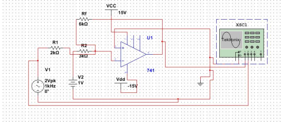
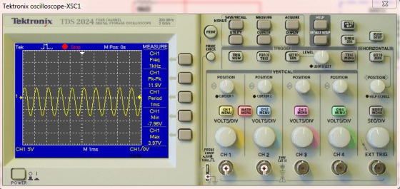
The input Waveform:-
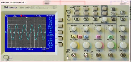
The Ouput Waveform:-
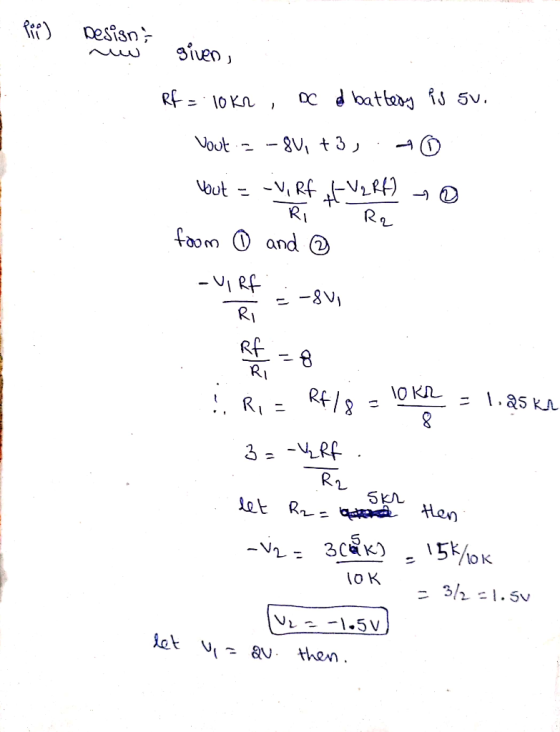
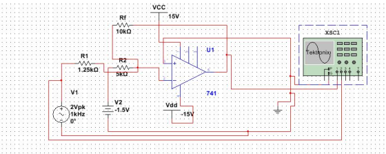
3)Design:-
Circuit:-
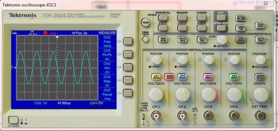
The Input Waveform:-
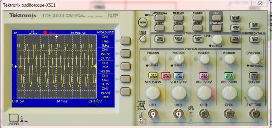
The Ouput Waveform:-
Add Answer to:
Problem # 3 For the summing opamp circuit, assume that the opamp is powered with +15V and-15V. Th...
Question 3 3 pts Focus on Op-amp U1 (Both op-amps have to be completely connected as...
 Question 3 3 pts Focus on Op-amp U1 (Both op-amps have to be completely connected as shown in Figure A) Use myDAQ's oscilloscope to capture the input waveform Vin (on Channel 0) and the intermediate output waveform Vout1 (on Channel 1) superimposed. Set the amplitude scale for both channels of the oscilloscope to 500 mV/Div Set the time scale of the oscilloscope to 200 us/Div 1. Take a screenshot of the oscilloscope (both waveform in the same picture) and embed...
Use the circuit diagram as shown in Figure A below to conduct the experiment and answer...
 Use the circuit diagram as shown in Figure A below to conduct the experiment and answer the questions 1 to 6. VCC VCC 15V 15V U2 U1 + R3 + 741 Voutt Vouth 6 R1 741 1.0kΩ 2.2k VEE VEE -15V Vin= 0.75 VIP-pl @ 2 kHz -15V R2 R4 TH 4.7ΚΩ 10kΩ Figure A Question 3 3 pts Focus on Op-amp U1 ("Both op-amps have to be completely connected as shown in Figure A) • Use myDAQ's oscilloscope to...
can you please solve this using a software simulator like multisim or something similar. just do...
 can you please solve this using a software simulator like
multisim or something similar.
just do it by calculation then
VCC VCC 15V 15V U2 U1 3 6 + R3 Voutt 741 = Vouth 6 R1 741 2 1.0kg 2.2k VEE -15V VEE Vin= -15V 2 0.75 VIP-P) @ 2 kHz R2 R4 4.7k02 10kΩ Figure A Focus on Op-amp U1 (*Both op-amps have to be completely connected as shown in Figure A) • Use myDAQ's oscilloscope to capture the...
can you please solve this using a software simulator like
multisim or something similar.
just do it by calculation then
VCC VCC 15V 15V U2 U1 3 6 + R3 Voutt 741 = Vouth 6 R1 741 2 1.0kg 2.2k VEE -15V VEE Vin= -15V 2 0.75 VIP-P) @ 2 kHz R2 R4 4.7k02 10kΩ Figure A Focus on Op-amp U1 (*Both op-amps have to be completely connected as shown in Figure A) • Use myDAQ's oscilloscope to capture the...
Use the circuit diagram as shown in Figure A below to conduct the experiment and answer...
 Use the circuit diagram as shown in Figure A below to conduct the experiment and answer the questions 1 to 6. VCC VCC 15V 15V U2 U1 + R3 + 741 Voutt Vouth 6 R1 741 1.0kΩ 2.2k VEE VEE -15V Vin= 0.75 VIP-pl @ 2 kHz -15V R2 R4 TH 4.7ΚΩ 10kΩ Figure A Question 5 3 pts Op-amp U1&U2 • Use myDAQ's oscilloscope to capture the input waveform Vin (on Channel O) and the final output waveform Vout2...
can you please solve this using a software simulator like multisim or something similar ?? VCC...
 can you please solve this using a software simulator like
multisim or something similar ??
VCC VCC 15V 15V U2 7 3 + U1 6 3 Vouth 741 R3 + Vout1 2 6 R1 741 2 1.0k 2 2.2k2 VEE -15V VEE -15V Vin= 0.75 Vp-p) @ 2 kHz R2 R4 4.7k2 10kΩ Figure A Op-amp U1&U2 • Use myDAQ's oscilloscope to capture the input waveform Vin (oh Channel 0) and the final output waveform Vout2 (on Channel 1) superintposed....
can you please solve this using a software simulator like
multisim or something similar ??
VCC VCC 15V 15V U2 7 3 + U1 6 3 Vouth 741 R3 + Vout1 2 6 R1 741 2 1.0k 2 2.2k2 VEE -15V VEE -15V Vin= 0.75 Vp-p) @ 2 kHz R2 R4 4.7k2 10kΩ Figure A Op-amp U1&U2 • Use myDAQ's oscilloscope to capture the input waveform Vin (oh Channel 0) and the final output waveform Vout2 (on Channel 1) superintposed....
Question 6 3 pts 1. Compare your experimental results to the previously-computed theoretical values. 2. Explain...
 Question 6 3 pts 1. Compare your experimental results to the previously-computed theoretical values. 2. Explain your observation from the oscilloscope output waveform. HTML Editor IEE xx E E A B I UA T ECE 12pt Paragraph Use the circuit diagram as shown in Figure A below to conduct the experiment and answer the questions 1 to 6. VCC VCC 15V 15V U2 U1 Voutt R3 1.0k Vout2 741 + 741 R1 2.2kQ VEE 4 VEE -15V Vin 0.75 V(p-p)...
Use the circuit diagram as shown in Figure A below to conduct the experiment and answer...
 Use the circuit diagram as shown in Figure A below to conduct the experiment and answer the questions 1 to 6. VCC VCC 15V 15V U2 U1 + R3 + 741 Voutt Vouth 6 R1 741 1.0kΩ 2.2k VEE VEE -15V Vin= 0.75 VIP-pl @ 2 kHz -15V R2 R4 TH 4.7ΚΩ 10kΩ Figure A Question 6 3 pts 1. Compare your experimental results to the previously-computed theoretical values. 2. Explain your observation from the oscilloscope output waveform. 12ptv Paragraph...
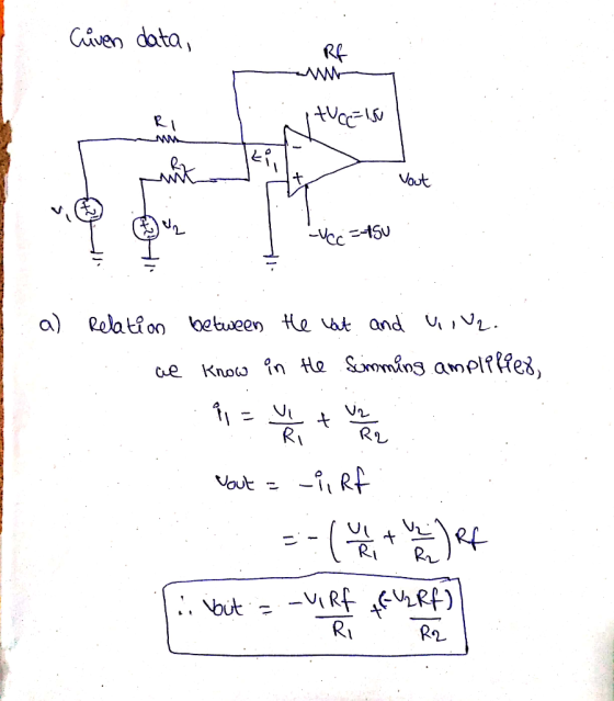
To obtain the difference between two different inputs, we can connect them to the positive and...
 To obtain the difference between two different inputs, we can connect them to the positive and negative pins of the Opamp. R1 7 +15V - opamp Ra AL15V Vout = 2 (U2-01) Where, R=R3 R2RA Figure 6: The difference amplifier The voltage follower is a non-inverting amplifier configuration with a gain of unity. Its output basically “follows” its input. The voltage follower's main virtue is that it has a very high input resistance. This is useful for driving a low...
can you please solve this using a software simulator lime multisimbor something similar. just do it...
 can you please solve this using a software simulator lime
multisimbor something similar.
just do it by calculations or use a software for circuit
simulation
Focus on Op-amp U2 ("Both op-amps have to be completely connected as shown in Figure A) • Use myDAQ's oscilloscope to capture the intermediate output waveform Vout1 (on Channel O) and the final output waveform Vout2 (on Channel 1) superimposed. • Set the amplitude scale of the oscilloscope for Channel O to 500 mV/Div, and...
can you please solve this using a software simulator lime
multisimbor something similar.
just do it by calculations or use a software for circuit
simulation
Focus on Op-amp U2 ("Both op-amps have to be completely connected as shown in Figure A) • Use myDAQ's oscilloscope to capture the intermediate output waveform Vout1 (on Channel O) and the final output waveform Vout2 (on Channel 1) superimposed. • Set the amplitude scale of the oscilloscope for Channel O to 500 mV/Div, and...
Problem #5 [10 points]: Design a circuit with the following criteria. Assume existence of +5V pow...
 Problem #5 [10 points]: Design a circuit with the following criteria. Assume existence of +5V power supply. Draw your circuit and show your work. i. Input signal that operates between Vin -5V- +5V, and capable of sourcing or sinking 500 x 10^-6 A. ii. Output signal nominally outputs between Vout 0V 5V, and capable of sinking 1 mA from an external device with an output no more than 0.1 V
Problem #5 [10 points]: Design a circuit with the following...
Problem #5 [10 points]: Design a circuit with the following criteria. Assume existence of +5V power supply. Draw your circuit and show your work. i. Input signal that operates between Vin -5V- +5V, and capable of sourcing or sinking 500 x 10^-6 A. ii. Output signal nominally outputs between Vout 0V 5V, and capable of sinking 1 mA from an external device with an output no more than 0.1 V
Problem #5 [10 points]: Design a circuit with the following...
 Question 3 3 pts Focus on Op-amp U1 (Both op-amps have to be completely connected as shown in Figure A) Use myDAQ's oscilloscope to capture the input waveform Vin (on Channel 0) and the intermediate output waveform Vout1 (on Channel 1) superimposed. Set the amplitude scale for both channels of the oscilloscope to 500 mV/Div Set the time scale of the oscilloscope to 200 us/Div 1. Take a screenshot of the oscilloscope (both waveform in the same picture) and embed...
 Use the circuit diagram as shown in Figure A below to conduct the experiment and answer the questions 1 to 6. VCC VCC 15V 15V U2 U1 + R3 + 741 Voutt Vouth 6 R1 741 1.0kΩ 2.2k VEE VEE -15V Vin= 0.75 VIP-pl @ 2 kHz -15V R2 R4 TH 4.7ΚΩ 10kΩ Figure A Question 3 3 pts Focus on Op-amp U1 ("Both op-amps have to be completely connected as shown in Figure A) • Use myDAQ's oscilloscope to...
 can you please solve this using a software simulator like
multisim or something similar.
just do it by calculation then
VCC VCC 15V 15V U2 U1 3 6 + R3 Voutt 741 = Vouth 6 R1 741 2 1.0kg 2.2k VEE -15V VEE Vin= -15V 2 0.75 VIP-P) @ 2 kHz R2 R4 4.7k02 10kΩ Figure A Focus on Op-amp U1 (*Both op-amps have to be completely connected as shown in Figure A) • Use myDAQ's oscilloscope to capture the...
can you please solve this using a software simulator like
multisim or something similar.
just do it by calculation then
VCC VCC 15V 15V U2 U1 3 6 + R3 Voutt 741 = Vouth 6 R1 741 2 1.0kg 2.2k VEE -15V VEE Vin= -15V 2 0.75 VIP-P) @ 2 kHz R2 R4 4.7k02 10kΩ Figure A Focus on Op-amp U1 (*Both op-amps have to be completely connected as shown in Figure A) • Use myDAQ's oscilloscope to capture the...
 Use the circuit diagram as shown in Figure A below to conduct the experiment and answer the questions 1 to 6. VCC VCC 15V 15V U2 U1 + R3 + 741 Voutt Vouth 6 R1 741 1.0kΩ 2.2k VEE VEE -15V Vin= 0.75 VIP-pl @ 2 kHz -15V R2 R4 TH 4.7ΚΩ 10kΩ Figure A Question 5 3 pts Op-amp U1&U2 • Use myDAQ's oscilloscope to capture the input waveform Vin (on Channel O) and the final output waveform Vout2...
 can you please solve this using a software simulator like
multisim or something similar ??
VCC VCC 15V 15V U2 7 3 + U1 6 3 Vouth 741 R3 + Vout1 2 6 R1 741 2 1.0k 2 2.2k2 VEE -15V VEE -15V Vin= 0.75 Vp-p) @ 2 kHz R2 R4 4.7k2 10kΩ Figure A Op-amp U1&U2 • Use myDAQ's oscilloscope to capture the input waveform Vin (oh Channel 0) and the final output waveform Vout2 (on Channel 1) superintposed....
can you please solve this using a software simulator like
multisim or something similar ??
VCC VCC 15V 15V U2 7 3 + U1 6 3 Vouth 741 R3 + Vout1 2 6 R1 741 2 1.0k 2 2.2k2 VEE -15V VEE -15V Vin= 0.75 Vp-p) @ 2 kHz R2 R4 4.7k2 10kΩ Figure A Op-amp U1&U2 • Use myDAQ's oscilloscope to capture the input waveform Vin (oh Channel 0) and the final output waveform Vout2 (on Channel 1) superintposed....
 Question 6 3 pts 1. Compare your experimental results to the previously-computed theoretical values. 2. Explain your observation from the oscilloscope output waveform. HTML Editor IEE xx E E A B I UA T ECE 12pt Paragraph Use the circuit diagram as shown in Figure A below to conduct the experiment and answer the questions 1 to 6. VCC VCC 15V 15V U2 U1 Voutt R3 1.0k Vout2 741 + 741 R1 2.2kQ VEE 4 VEE -15V Vin 0.75 V(p-p)...
 Use the circuit diagram as shown in Figure A below to conduct the experiment and answer the questions 1 to 6. VCC VCC 15V 15V U2 U1 + R3 + 741 Voutt Vouth 6 R1 741 1.0kΩ 2.2k VEE VEE -15V Vin= 0.75 VIP-pl @ 2 kHz -15V R2 R4 TH 4.7ΚΩ 10kΩ Figure A Question 6 3 pts 1. Compare your experimental results to the previously-computed theoretical values. 2. Explain your observation from the oscilloscope output waveform. 12ptv Paragraph...
 To obtain the difference between two different inputs, we can connect them to the positive and negative pins of the Opamp. R1 7 +15V - opamp Ra AL15V Vout = 2 (U2-01) Where, R=R3 R2RA Figure 6: The difference amplifier The voltage follower is a non-inverting amplifier configuration with a gain of unity. Its output basically “follows” its input. The voltage follower's main virtue is that it has a very high input resistance. This is useful for driving a low...
 can you please solve this using a software simulator lime
multisimbor something similar.
just do it by calculations or use a software for circuit
simulation
Focus on Op-amp U2 ("Both op-amps have to be completely connected as shown in Figure A) • Use myDAQ's oscilloscope to capture the intermediate output waveform Vout1 (on Channel O) and the final output waveform Vout2 (on Channel 1) superimposed. • Set the amplitude scale of the oscilloscope for Channel O to 500 mV/Div, and...
can you please solve this using a software simulator lime
multisimbor something similar.
just do it by calculations or use a software for circuit
simulation
Focus on Op-amp U2 ("Both op-amps have to be completely connected as shown in Figure A) • Use myDAQ's oscilloscope to capture the intermediate output waveform Vout1 (on Channel O) and the final output waveform Vout2 (on Channel 1) superimposed. • Set the amplitude scale of the oscilloscope for Channel O to 500 mV/Div, and...
 Problem #5 [10 points]: Design a circuit with the following criteria. Assume existence of +5V power supply. Draw your circuit and show your work. i. Input signal that operates between Vin -5V- +5V, and capable of sourcing or sinking 500 x 10^-6 A. ii. Output signal nominally outputs between Vout 0V 5V, and capable of sinking 1 mA from an external device with an output no more than 0.1 V
Problem #5 [10 points]: Design a circuit with the following...
Problem #5 [10 points]: Design a circuit with the following criteria. Assume existence of +5V power supply. Draw your circuit and show your work. i. Input signal that operates between Vin -5V- +5V, and capable of sourcing or sinking 500 x 10^-6 A. ii. Output signal nominally outputs between Vout 0V 5V, and capable of sinking 1 mA from an external device with an output no more than 0.1 V
Problem #5 [10 points]: Design a circuit with the following...
Most questions answered within 3 hours.
-
To be done in java code. 2 words are anagrams if 1 word can be
formed...
asked 5 minutes ago -
Bright Sun, Inc. sold an issue of 30-year $1,000 par value bonds
to the public. The...
asked 2 minutes ago -
Two players take turns at removing 1 to 4 coins from an original
pile of 16...
asked 2 minutes ago -
The income statement for the month of June, 2014 of Happy Smiles
Enterprises contains the following...
asked 8 minutes ago -
1-Calculate the mass in grams of 2.55 moles of KCl
2- Calculate how many moles are...
asked 8 minutes ago -
1. Choose value for p between 0.20 and 0.80. It should have at
least two decimal...
asked 10 minutes ago -
QUESTIONS: 500 words for the question
In defining abnormality, the criteria of “deviance”, “distress”
and “dysfunction”...
asked 11 minutes ago -
A sample of n = 25 scores produces a t statistic of t =
-2.062. If...
asked 29 minutes ago -
Given the following, compute the after tax cost of debt: The par
value of the firms...
asked 22 minutes ago -
Coding in C. Please only use stdio.h (which would mean no malloc
or anything like that)...
asked 28 minutes ago -
Use the fundamental accounting equation to find the missing
amounts.
Scenario
Assets
Liabilities
Equity
1
$...
asked 26 minutes ago -
A population has a mean of 200 and a standard deviation of 60.
Suppose a sample...
asked 30 minutes ago