use variation of parameters and substitution to find solutions to word problems
use technique described on page
please complete questions circled in the page

Homework Answers


Add Answer to:
Use variation of parameters and substitution to find solutions to word problems use technique des...
use variation of parameters and substituion to find solutions to word problems use technique decribed on...
 use variation of parameters and substituion to find solutions
to word problems
use technique decribed on page
please complete questions circled in the page
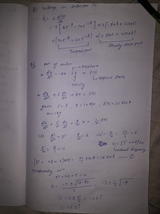
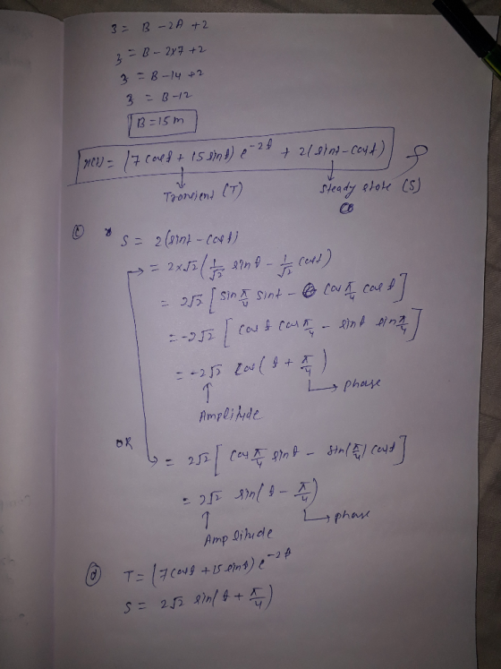
Spring : m = k(T-T,n) RLC current : Lan-R di dVc dt 6. F gram mass on a spring with spring constant k 10 N/m, and resistance of 8 times the velocity, suppose there is an applied force of f(t) - 32sin(t) N. (a) Solve for the position of the spring (t) if is initially at...
use variation of parameters and substituion to find solutions
to word problems
use technique decribed on page
please complete questions circled in the page
Spring : m = k(T-T,n) RLC current : Lan-R di dVc dt 6. F gram mass on a spring with spring constant k 10 N/m, and resistance of 8 times the velocity, suppose there is an applied force of f(t) - 32sin(t) N. (a) Solve for the position of the spring (t) if is initially at...
1. RLC Circuits Revisited. The first example of a RLC circuit illustrates the use of circuit...
 1. RLC Circuits Revisited. The first example of a RLC circuit illustrates the use of circuit elements in the s domain to represent initial conditions and a forced response. Next an example of sinusoidal excitation will follow where the transient response and steady state response are combined into one response waveform.. Transient RLC Circuit with Initial Conditions. Consider the RLC circuit below in Figure 7.14 which has two DC sources (Vco and V) applied before and after a switch is...
Please help solve while providing a detailed solution. Being given the following information, use the equations...
 Please help solve while providing a detailed solution.
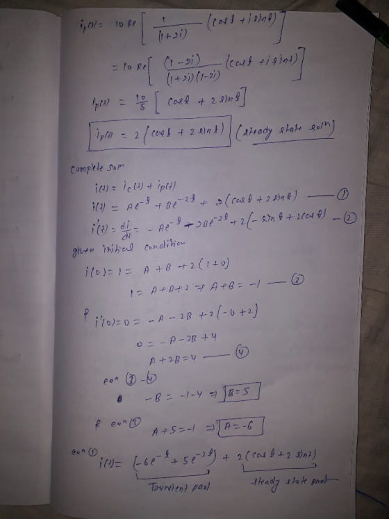
Being given the following information, use the equations provided to find the steady-state current in the following RLC circuit. R=82 L= 0.5H C= 0.1F E(t) = 100 cos(2t) V knowing that at t = 0, i(0) = 0 Equations: UR = Ri VL = = L- di 9 Uci dt С VR + V1 + Vc = e(t) or =V (if the source voltage is constant) dq duc i= = C- q=ſidt...
Please help solve while providing a detailed solution.
Being given the following information, use the equations provided to find the steady-state current in the following RLC circuit. R=82 L= 0.5H C= 0.1F E(t) = 100 cos(2t) V knowing that at t = 0, i(0) = 0 Equations: UR = Ri VL = = L- di 9 Uci dt С VR + V1 + Vc = e(t) or =V (if the source voltage is constant) dq duc i= = C- q=ſidt...
Please help solve, providing a detailed solution using the equations provided below and LaPlace transform (Use...
 Please help solve, providing a detailed solution using the
equations provided below and
LaPlace transform (Use the table provided in the
link) to solve the differential equations obtained when working
through the question.
Link to the Laplace Transform Table:
https://ibb.co/TkrvbNH
Being given the following information, use the equations provided to find the steady-state current in the following RLC circuit. R=82 L= 0.5H C= 0.1F E(t) = 100 cos(2t) V knowing that at t = 0, i(0) = 0 Equations: UR...
Please help solve, providing a detailed solution using the
equations provided below and
LaPlace transform (Use the table provided in the
link) to solve the differential equations obtained when working
through the question.
Link to the Laplace Transform Table:
https://ibb.co/TkrvbNH
Being given the following information, use the equations provided to find the steady-state current in the following RLC circuit. R=82 L= 0.5H C= 0.1F E(t) = 100 cos(2t) V knowing that at t = 0, i(0) = 0 Equations: UR...
Please help me to solve it... And what is the weird symbol used in the solution??...
 Please help me to solve it... And what is the weird
symbol used in the solution??
L- dI + Ri et dt konditoriohm) Lo Series with R = thyernton (ohm) L Inductor (Henrys) E source of electro motive force that supplies a voltage (volt) t = time. 1 = curent (ampere) Following 25. a resistor-indu Cher (RL) series surir, circuit. R-6 ohm 9 L = 6henrys. e(t) = 12 volts. switch off t=0, I = 0 Ampere Find I(t) if...
Please help me to solve it... And what is the weird
symbol used in the solution??
L- dI + Ri et dt konditoriohm) Lo Series with R = thyernton (ohm) L Inductor (Henrys) E source of electro motive force that supplies a voltage (volt) t = time. 1 = curent (ampere) Following 25. a resistor-indu Cher (RL) series surir, circuit. R-6 ohm 9 L = 6henrys. e(t) = 12 volts. switch off t=0, I = 0 Ampere Find I(t) if...
R t = i(t) C 2011P E e p gP a P9.09 10ed The voltage applied...
 R t = i(t) C 2011P E e p gP a P9.09 10ed The voltage applied to this circuit at t 0 (when the switch closes) is v (t) = 75 cos (4,000t - 60°) Volts Also given that R = 400 2 (0hm) and L=75 mH (milli Henry) The initial inductor current is zero for t< 0 The textbook gives you the total response equation as: )_ ?(0-¢)so R2+(w L) Cos(wt+¢-e) -V V m i(t)=itransient(t)+isteady.state(t)=R2 +(wL m - ㅎCOS...
An RLC circuit contains in series a resistor R = 3 Ω, an inductor L =...
An RLC circuit contains in series a resistor R = 3 Ω, an inductor L = 1 H, and a capacitor C = 0.5 F. The current I(t) is provided by a source with emf E = 20cos(2t) Volts, where t is the time. Find the steady-state current Ip that develops after a long time (theoretically when t → ∞).
2. This problem is about an RLC circuit, which involves a resistor (of resistance R ohms),...
 2. This problem is about an RLC circuit, which involves a resistor (of resistance R ohms), an inductor (of L henries), and a capacitor (of C farads). There is also a voltage source (such as a battery) providing E(t) volts at time t. 0 Switch When the switch is closed there is a current of I(t) amperes. With the help of Kirchhoff's laws one can derive an ODE for I = I(t): LI" + RI' + + I = E'(t)...
find response of the parallel RLC circuit on Figure 3. Sketch iL(t) for tE( 0, 50us)...
 find response of the parallel RLC circuit on Figure 3. Sketch iL(t)
for tE( 0, 50us)
initial voltage on the capacitor Vo = 10v.
initial current in the inductor is 100mA.
current source is 100mA.
(Please order all steps so I know how to approach a problem
like this)
Find response of the Parallel RLC circuit on Figure 3. Sketch iz(t) fort € (0, 50uS) Initial Voltage on the capacitor Vo=10V Initial curent in the inductor is 100mA Current Source...
find response of the parallel RLC circuit on Figure 3. Sketch iL(t)
for tE( 0, 50us)
initial voltage on the capacitor Vo = 10v.
initial current in the inductor is 100mA.
current source is 100mA.
(Please order all steps so I know how to approach a problem
like this)
Find response of the Parallel RLC circuit on Figure 3. Sketch iz(t) fort € (0, 50uS) Initial Voltage on the capacitor Vo=10V Initial curent in the inductor is 100mA Current Source...
PROBLEM 5. TUNING A CIRCUIT: PRACTICAL RESONANCE. Consider a forced RLC circuit with L-1 (H), R-1...
 PROBLEM 5. TUNING A CIRCUIT: PRACTICAL RESONANCE. Consider a forced RLC circuit with L-1 (H), R-10 (12) and C 丽0 (f). Suppose an alternating current supplies a electromotive force Et)100 coswt. The equation modeling the charge Q(t) on the capacitor is 650 Q"(t) 10Q650Q(t) 100 coswt. a. Is the damping over-, under- or critical? Find the form of the general solution. Identify the transient and steady-state parts of the solution. b. Find the amplitude C(w) of the steady-state piece (here...
 use variation of parameters and substituion to find solutions
to word problems
use technique decribed on page
please complete questions circled in the page
Spring : m = k(T-T,n) RLC current : Lan-R di dVc dt 6. F gram mass on a spring with spring constant k 10 N/m, and resistance of 8 times the velocity, suppose there is an applied force of f(t) - 32sin(t) N. (a) Solve for the position of the spring (t) if is initially at...
use variation of parameters and substituion to find solutions
to word problems
use technique decribed on page
please complete questions circled in the page
Spring : m = k(T-T,n) RLC current : Lan-R di dVc dt 6. F gram mass on a spring with spring constant k 10 N/m, and resistance of 8 times the velocity, suppose there is an applied force of f(t) - 32sin(t) N. (a) Solve for the position of the spring (t) if is initially at...
 1. RLC Circuits Revisited. The first example of a RLC circuit illustrates the use of circuit elements in the s domain to represent initial conditions and a forced response. Next an example of sinusoidal excitation will follow where the transient response and steady state response are combined into one response waveform.. Transient RLC Circuit with Initial Conditions. Consider the RLC circuit below in Figure 7.14 which has two DC sources (Vco and V) applied before and after a switch is...
 Please help solve while providing a detailed solution.
Being given the following information, use the equations provided to find the steady-state current in the following RLC circuit. R=82 L= 0.5H C= 0.1F E(t) = 100 cos(2t) V knowing that at t = 0, i(0) = 0 Equations: UR = Ri VL = = L- di 9 Uci dt С VR + V1 + Vc = e(t) or =V (if the source voltage is constant) dq duc i= = C- q=ſidt...
Please help solve while providing a detailed solution.
Being given the following information, use the equations provided to find the steady-state current in the following RLC circuit. R=82 L= 0.5H C= 0.1F E(t) = 100 cos(2t) V knowing that at t = 0, i(0) = 0 Equations: UR = Ri VL = = L- di 9 Uci dt С VR + V1 + Vc = e(t) or =V (if the source voltage is constant) dq duc i= = C- q=ſidt...
 Please help solve, providing a detailed solution using the
equations provided below and
LaPlace transform (Use the table provided in the
link) to solve the differential equations obtained when working
through the question.
Link to the Laplace Transform Table:
https://ibb.co/TkrvbNH
Being given the following information, use the equations provided to find the steady-state current in the following RLC circuit. R=82 L= 0.5H C= 0.1F E(t) = 100 cos(2t) V knowing that at t = 0, i(0) = 0 Equations: UR...
Please help solve, providing a detailed solution using the
equations provided below and
LaPlace transform (Use the table provided in the
link) to solve the differential equations obtained when working
through the question.
Link to the Laplace Transform Table:
https://ibb.co/TkrvbNH
Being given the following information, use the equations provided to find the steady-state current in the following RLC circuit. R=82 L= 0.5H C= 0.1F E(t) = 100 cos(2t) V knowing that at t = 0, i(0) = 0 Equations: UR...
 Please help me to solve it... And what is the weird
symbol used in the solution??
L- dI + Ri et dt konditoriohm) Lo Series with R = thyernton (ohm) L Inductor (Henrys) E source of electro motive force that supplies a voltage (volt) t = time. 1 = curent (ampere) Following 25. a resistor-indu Cher (RL) series surir, circuit. R-6 ohm 9 L = 6henrys. e(t) = 12 volts. switch off t=0, I = 0 Ampere Find I(t) if...
Please help me to solve it... And what is the weird
symbol used in the solution??
L- dI + Ri et dt konditoriohm) Lo Series with R = thyernton (ohm) L Inductor (Henrys) E source of electro motive force that supplies a voltage (volt) t = time. 1 = curent (ampere) Following 25. a resistor-indu Cher (RL) series surir, circuit. R-6 ohm 9 L = 6henrys. e(t) = 12 volts. switch off t=0, I = 0 Ampere Find I(t) if...
 R t = i(t) C 2011P E e p gP a P9.09 10ed The voltage applied to this circuit at t 0 (when the switch closes) is v (t) = 75 cos (4,000t - 60°) Volts Also given that R = 400 2 (0hm) and L=75 mH (milli Henry) The initial inductor current is zero for t< 0 The textbook gives you the total response equation as: )_ ?(0-¢)so R2+(w L) Cos(wt+¢-e) -V V m i(t)=itransient(t)+isteady.state(t)=R2 +(wL m - ㅎCOS...
 2. This problem is about an RLC circuit, which involves a resistor (of resistance R ohms), an inductor (of L henries), and a capacitor (of C farads). There is also a voltage source (such as a battery) providing E(t) volts at time t. 0 Switch When the switch is closed there is a current of I(t) amperes. With the help of Kirchhoff's laws one can derive an ODE for I = I(t): LI" + RI' + + I = E'(t)...
 find response of the parallel RLC circuit on Figure 3. Sketch iL(t)
for tE( 0, 50us)
initial voltage on the capacitor Vo = 10v.
initial current in the inductor is 100mA.
current source is 100mA.
(Please order all steps so I know how to approach a problem
like this)
Find response of the Parallel RLC circuit on Figure 3. Sketch iz(t) fort € (0, 50uS) Initial Voltage on the capacitor Vo=10V Initial curent in the inductor is 100mA Current Source...
find response of the parallel RLC circuit on Figure 3. Sketch iL(t)
for tE( 0, 50us)
initial voltage on the capacitor Vo = 10v.
initial current in the inductor is 100mA.
current source is 100mA.
(Please order all steps so I know how to approach a problem
like this)
Find response of the Parallel RLC circuit on Figure 3. Sketch iz(t) fort € (0, 50uS) Initial Voltage on the capacitor Vo=10V Initial curent in the inductor is 100mA Current Source...
 PROBLEM 5. TUNING A CIRCUIT: PRACTICAL RESONANCE. Consider a forced RLC circuit with L-1 (H), R-10 (12) and C 丽0 (f). Suppose an alternating current supplies a electromotive force Et)100 coswt. The equation modeling the charge Q(t) on the capacitor is 650 Q"(t) 10Q650Q(t) 100 coswt. a. Is the damping over-, under- or critical? Find the form of the general solution. Identify the transient and steady-state parts of the solution. b. Find the amplitude C(w) of the steady-state piece (here...
Most questions answered within 3 hours.
-
The average length of time between arrivals at a turnpike
toll-booth is 26 seconds. What is...
asked 30 minutes ago -
(a) A piston at 6.1 atm contains a gas that occupies a volume of
3.5 L....
asked 1 hour ago -
Please answer true or false. Words
cannot be changed or added in to make it true...
asked 1 hour ago -
An empty test tube weighs 15.923 grams. Then,
MgCl2•6H2O is added into the test tube. After...
asked 1 hour ago -
Assume memory access is 10 units of time and disk access is
10000 units of time....
asked 2 hours ago -
1. Are all good samples random?
2. Magazines often report surveys giving statistics such as “63%...
asked 2 hours ago -
Under all the various types of market structures, firms
must eventually earn some economic profits for...
asked 2 hours ago -
Consider the following fitness regime for a single locus trait
with two co-dominant alleles: w11 =...
asked 2 hours ago -
A large cable company reports the following.
80% of its customers subscribe to its cable TV...
asked 2 hours ago -
Please answer the question in brief.
Discuss the role of ERP in organizations. Are ERP tools...
asked 2 hours ago -
Discuss the pros and cons of collaborative software such
as SameTime. Does it increase productivity? What...
asked 2 hours ago -
Buying your in-laws a gift because it’s expected is
due to the ____________ motive of gift-giving....
asked 2 hours ago