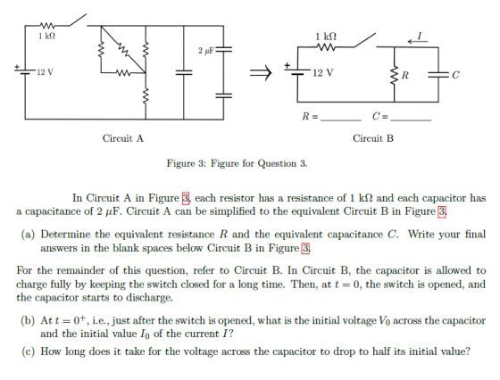
In Circuit \(\mathrm{A}\) in Figure 3, each resistor has a resistance of \(1 \mathrm{k} \Omega\) and each capacitor has a capacitance of \(2 \mu \mathrm{F}\). Circuit A can be simplified to the equivalent Circuit B in Figure 3 .
(a) Determine the equivalent resistance R and the equivalent capacitance C. Write your final answers in the blank spaces below Circuit B in Figure 3 .
For the remainder of this question, refer to Circuit \(\mathrm{B}\). In Circuit \(\mathrm{B}\), the capacitor is allowed to charge fully by keeping the switch closed for a long time. Then, at \(t=0\), the switch is opened, and the capacitor starts to discharge.
(b) At \(t=0^{+}\), i.e., just after the switch is opened, what is the initial voltage \(V_{0}\) across the capacitor and the initial value \(I_{0}\) of the current \(I ?\)
(c) How long does it take for the voltage across the capacitor to drop to half its initial value?
Homework Answers


Add Answer to:
Determine the equivalent resistance R and the equivalent capacitance C
If both questions can be answeredthanks!Find the Equivalent Resistance Four resistors are connected as...
 Find the Equivalent ResistanceFour resistors are connected as shown in figure (a), below. (Let R=3.00 Ω.)The original network of resistors is reduced to a single equivalent resistance.(a) Find the equivalent resistance between points \(a\) and \(\mathrm{c}\).solutionConceptualize Imagine charges flowing into and through this combination from the left. All charges must pass from a to \(b\) through the first two resistors, but the charges split at \(b\) into Categorize Because of the simple nature of the combination of resistors in the...
Problem 7 A resistor with resistance R, battery with voltage AV, capacitor with capacitance C, and...
 Problem 7 A resistor with resistance R, battery with voltage AV, capacitor with capacitance C, and switch are connected in series. The switch is closed at t = 0. The time constant of the circuit is T. What is the initial voltage across the resistor immediately after the student is closed? Select One of the Following: (a) o (b) AV (c) TAV (d) AV/T (e) AV/(R+C) Problem 8 A capacitor is charged to potential difference V and then allowed to...
Consider a series circuit containing a resistor of resistance R and a capacitor of capacitance C connected to a source of EMF ε with negligible internal resistance.
 Consider a series circuit containing a resistor of resistance R and a capacitor of capacitance C connected to a source of EMF ε with negligible internal resistance. The wires are also assumed to have zero resistance. Initially, the switch is open and the capacitor discharged. (Figure 1)Immediately after the switch is closed, what is the voltage
across the resistor?Immediately after the switch is closed, what is the direction of
the current in the circuit?
Consider a series circuit containing a resistor of resistance R and a capacitor of capacitance C connected to a source of EMF ε with negligible internal resistance. The wires are also assumed to have zero resistance. Initially, the switch is open and the capacitor discharged. (Figure 1)Immediately after the switch is closed, what is the voltage
across the resistor?Immediately after the switch is closed, what is the direction of
the current in the circuit?
Consider a series circuit containing a resistor of resistance R and a capacitor of capacitance C connected to a source of EMF E with negligible internal resistance.
 Consider a series circuit containing a resistor of resistance R and a capacitor of capacitance C connected to a source of EMF E with negligible internal resistance. The wires are also assumed to have zero resistance. Initially, the switch is open and the capacitor discharged. (Figure 1)A Immediately after the switch is closed, what is the voltage across the capacitor?B Complete previous part(s) C Immediately after the switch is closed, what is the direction of the current in the circuit? E Eventually,...
A simply RC circuit made up of a capacitor with capacitance C and resistor with resistance...
A simply RC circuit made up of a capacitor with capacitance C and resistor with resistance R = 15 kΩ is attached to a battery with emf E = 24 V. If time constant is 25 µs, what is the capacitance C and the time it takes for the voltage across the capacitor to reach 16 V after the switch is closed at t = 0?
A capacitor with capacitance C is initially charged with charge q0. At time t = 0 a resistor with resistance R is connected across the capacitor. (Figure 1)
 To understand the behavior of the current and voltage in a simple R-C circuit. A capacitor with capacitance C is initially charged with charge q0. At time t = 0 a resistor with resistance R is connected across the capacitor. (Figure 1) Part CNow solve the differential equation V(t) = -CR dV(t)/dt for the initial conditions given in the problem introduction to find the voltage as a function of time for any time t.
5. A resistance 250, inductance 200mH, and capacitance 1 uF capacitor are all connected in series,...
 5. A resistance 250, inductance 200mH, and capacitance 1 uF capacitor are all connected in series, and across the combination is connected to a 500V, 60 Hz supply. Calculate (a) the current flowing, (b) the phase difference between the supply voltage and current, (c) the voltage across the coil and the capacitor. 6. An 300-uF capacitor is connected in series with 3.25-MQ resistance across a 300-V supply. The switch is closed. Calculate a) Time constant of the circuit b) Initial...
for the current shown find a) the equivalent resistance of the circuit 28. The capacitor in...
 for the current shown find a) the equivalent resistance of the
circuit
28. The capacitor in the figure shown is initially uncharged and the switch, in position is not connected to either side of the circuit. The switch is now flipped to position a for 10 ms, (a) What is voltage difference across the capacitor? (b) then the switch flipped to position b for 10 ms and then brought back to position c. What the final voltage difference across the...
for the current shown find a) the equivalent resistance of the
circuit
28. The capacitor in the figure shown is initially uncharged and the switch, in position is not connected to either side of the circuit. The switch is now flipped to position a for 10 ms, (a) What is voltage difference across the capacitor? (b) then the switch flipped to position b for 10 ms and then brought back to position c. What the final voltage difference across the...
Answer: 96. Consider the circuit below. The capacitor has a capacitance of 10 mF. The switch...
 Answer:
96. Consider the circuit below. The capacitor has a capacitance of 10 mF. The switch is closed and after a long time the capacitor is fully charged. (a) What is the current through each resistor a long time after the switch is closed? (b) What is the voltage across each resistor a long time after the switch is closed? (c) What is the voltage across the capacitor a long time after the switch is closed? (d) What is the...
Answer:
96. Consider the circuit below. The capacitor has a capacitance of 10 mF. The switch is closed and after a long time the capacitor is fully charged. (a) What is the current through each resistor a long time after the switch is closed? (b) What is the voltage across each resistor a long time after the switch is closed? (c) What is the voltage across the capacitor a long time after the switch is closed? (d) What is the...
7 A circuit consists of a resistor of resistance R, and a capacitor of capacitance C,...
 7 A circuit consists of a resistor of resistance R, and a capacitor of capacitance C, connected in series, and is described by the first order differential equation - + y = E where E is the constant e.m.f. and v is the voltage across the capacitor. Given that v(O) = 0, show by using the integrating factor method that v = E(1 - e-t/(RC))
 Problem 7 A resistor with resistance R, battery with voltage AV, capacitor with capacitance C, and switch are connected in series. The switch is closed at t = 0. The time constant of the circuit is T. What is the initial voltage across the resistor immediately after the student is closed? Select One of the Following: (a) o (b) AV (c) TAV (d) AV/T (e) AV/(R+C) Problem 8 A capacitor is charged to potential difference V and then allowed to...
 5. A resistance 250, inductance 200mH, and capacitance 1 uF capacitor are all connected in series, and across the combination is connected to a 500V, 60 Hz supply. Calculate (a) the current flowing, (b) the phase difference between the supply voltage and current, (c) the voltage across the coil and the capacitor. 6. An 300-uF capacitor is connected in series with 3.25-MQ resistance across a 300-V supply. The switch is closed. Calculate a) Time constant of the circuit b) Initial...
 for the current shown find a) the equivalent resistance of the
circuit
28. The capacitor in the figure shown is initially uncharged and the switch, in position is not connected to either side of the circuit. The switch is now flipped to position a for 10 ms, (a) What is voltage difference across the capacitor? (b) then the switch flipped to position b for 10 ms and then brought back to position c. What the final voltage difference across the...
for the current shown find a) the equivalent resistance of the
circuit
28. The capacitor in the figure shown is initially uncharged and the switch, in position is not connected to either side of the circuit. The switch is now flipped to position a for 10 ms, (a) What is voltage difference across the capacitor? (b) then the switch flipped to position b for 10 ms and then brought back to position c. What the final voltage difference across the...
 Answer:
96. Consider the circuit below. The capacitor has a capacitance of 10 mF. The switch is closed and after a long time the capacitor is fully charged. (a) What is the current through each resistor a long time after the switch is closed? (b) What is the voltage across each resistor a long time after the switch is closed? (c) What is the voltage across the capacitor a long time after the switch is closed? (d) What is the...
Answer:
96. Consider the circuit below. The capacitor has a capacitance of 10 mF. The switch is closed and after a long time the capacitor is fully charged. (a) What is the current through each resistor a long time after the switch is closed? (b) What is the voltage across each resistor a long time after the switch is closed? (c) What is the voltage across the capacitor a long time after the switch is closed? (d) What is the...
 7 A circuit consists of a resistor of resistance R, and a capacitor of capacitance C, connected in series, and is described by the first order differential equation - + y = E where E is the constant e.m.f. and v is the voltage across the capacitor. Given that v(O) = 0, show by using the integrating factor method that v = E(1 - e-t/(RC))
Most questions answered within 3 hours.
-
Roybus, Inc., a manufacturer of flash memory, just reported that
its main production facility in Taiwan...
asked 3 minutes ago -
Two capacitors connected in parallel produce an equivalent
capacitance of 45.0 μF but when connected in...
asked 12 minutes ago -
The differences between the two sets of dependent data are -1,
2,-,2, 2. Round to the...
asked 29 minutes ago -
A χ2-curve, looking at the relationship between age and hours
spent working at an office per...
asked 1 hour ago -
The pH of a sample of water from a river is 5.0. A
sample of effluent from...
asked 1 hour ago -
At the beginning of the period, the Fabricating Department
budgeted direct labor of $136,500 and equipment...
asked 2 hours ago -
Please answer all
____ 28. Rent control is usually
justified on the grounds that it protects...
asked 2 hours ago -
PARTS A-D HAVE BEEN ANSWERED. WAS TOLD TO REPOST. ONLY ANSWER
PARTS E and F.
A...
asked 2 hours ago -
2) You are given the task of finding a representation for a
circle in a drawing...
asked 3 hours ago -
STUDY QUESTION: Does use of diet drug fen-phen
(fenfluramine-phentermine) cause valvular heart disease?
HINT: Valvular heart...
asked 3 hours ago -
1. An object weighing 40 N rests on a surface. The coefficient
of friction is 0.35....
asked 4 hours ago -
Investor company owns 35% of investee company voting stock and
accounts for the investment under the...
asked 5 hours ago