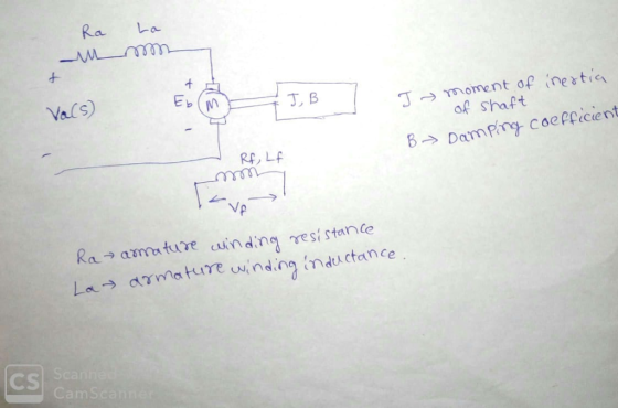
The simplified (first order) transfer function model of the DC motor between the shaft spe ed ( (...
The
simplified (first order) transfer function model of the DC motor between the shaft spe
ed (
()
s
) and
the armature voltage (
()
a
Vs
)
Homework Answers
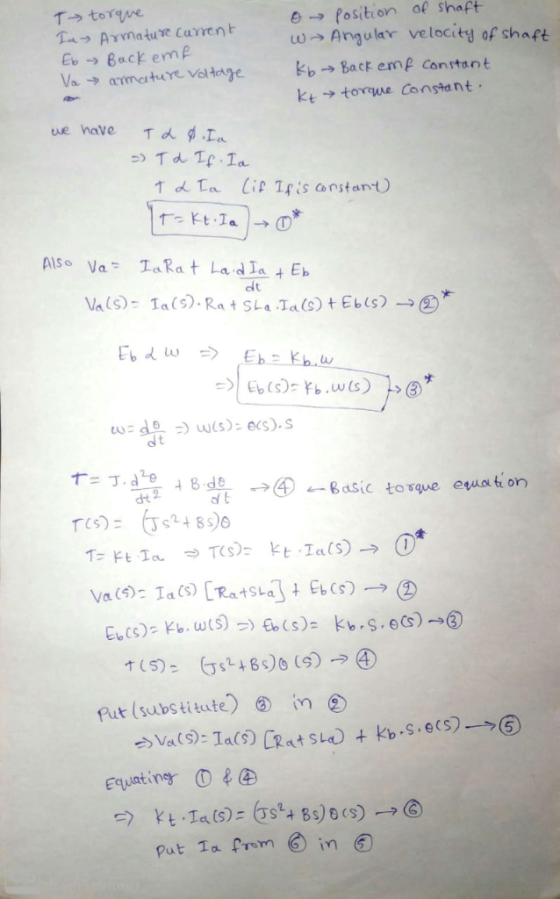
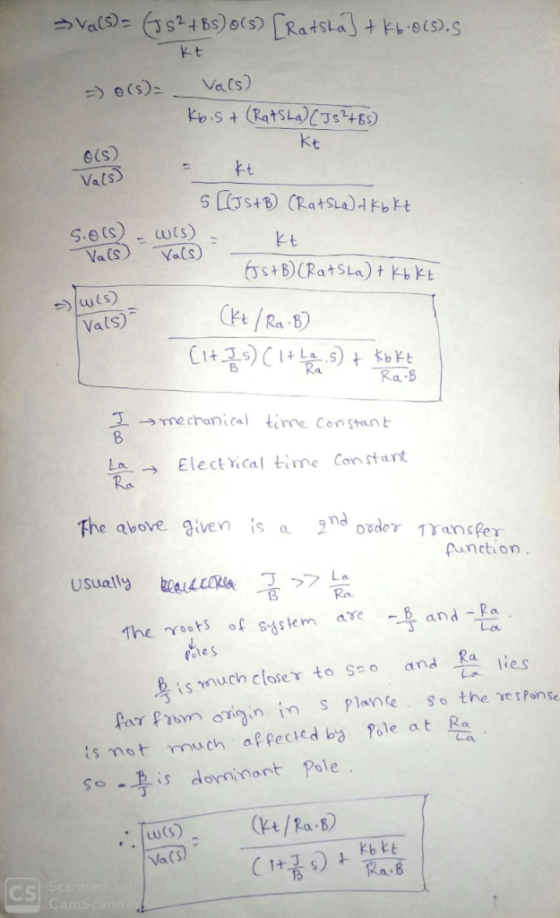
First I'll derive the actual 2nd order transfer function and then I'll tell you the approximation for obtaining first-order transfer function for angular speed of the shaft
Add Answer to:
The simplified (first order) transfer function model of the DC motor between the shaft spe ed ( (...
The simplified diagram of a DC motor is shown in Fig. 4. Assume that the rotor has inertia m J an...
 The simplified diagram of a DC motor is shown in Fig. 4. Assume
that the rotor has inertia m J and viscous friction coefficient Bm.
The torque developed by the motor is assumed to be related linearly
to the field current by , m m f T K i where the motor torque
constant m f a K K K I 1 when the armature current a i is assumed
constant (i.e. ) a a i I...
The simplified diagram of a DC motor is shown in Fig. 4. Assume
that the rotor has inertia m J and viscous friction coefficient Bm.
The torque developed by the motor is assumed to be related linearly
to the field current by , m m f T K i where the motor torque
constant m f a K K K I 1 when the armature current a i is assumed
constant (i.e. ) a a i I...
Problem-5 (20 pts): Consider the DC servo motor shown in Figure-5. Assume that the input of the s...
 Problem-5 (20 pts): Consider the DC servo motor shown in Figure-5. Assume that the input of the system is the applied armature voltage ea and the output is the load shaft position θ2. Assume also the following numerical values for the components: Ra-) Armature winding resistance = 0.2Ω La → Armature winding inductance = 0.1 mH Kb-) Back emf constant 0.05 Vs/rad K > Motor torque constant 0.06 Nm/A Jr Moment of inertia of the rotor of the motor =...
A permanent magnet DC motor is supplied from a 12 V source and turns at 500...
 A permanent magnet DC motor is supplied from a 12 V source and turns at 500 RPM (steady-state) experimentally determined as 0.1 Nms2 and the frictions are negligible. The electrical parameters of the rotor winding are measured 0.82, and 5mH. Obtain the transfer function of the motor by considering the armature voltage as input and shaft speed in rad/s as output. with an armature current of 1A. The moment of inertia is
(30 pts) A D.C. motor is shown below, where the inductance L and the resistance R model the armat...
 (30 pts) A D.C. motor is shown below, where the inductance L and the resistance R model the armature circuit. The voltage Vb represents the back-emf which is proportional to dθ/dt via K. The torque T generated by the motor is proportional to the i via a constant K. The inertia J represents the combined inertia of the motor and load. The viscous friction acting on the output shaft is B 1. pur voltaop a. A. (10 pts) Find the...
Figure Q1(b) shows the simplified diagram of the armature controlled D.C. b) servomotors used in instruments...
 Figure Q1(b) shows the simplified diagram of the armature controlled D.C. b) servomotors used in instruments and employed a fixed permane nt magnet field. The control signal is app lied to the amature terminals. The inductance of armature winding is negligible. Obtain the transfer function of the servo mot or (assume K, K, and K, are constant) i) (10marks) Derive a state spa ce model for the servomotor (armature resistance is 0.2) (5marks) i) La Fixed field (if) Ra ww00...
Problem 2: (30 points) A mode ontrolled DC motor is she l or is shown below....
 Problem 2: (30 points) A mode ontrolled DC motor is she l or is shown below. The em 2: (30 points) A model of an armature contro aller, here modeled as a rigid body with mass load attached to the rotor of the motor is a prope is transmitted to the propeller through a shaft moment of inertia IL. The rotation of the rotor with torsional damping constant br. The proper eller motion generate a further load TL due to...
Question 3: DC motors can be simplistically modeled as shown in Figure 5 MoTor back emf Vi: +1 Re...
 Question 3: DC motors can be simplistically modeled as shown in Figure 5 MoTor back emf Vi: +1 Resistor Ra Ia Figure 5: Simplified model of DC Motor (a) Write the three characteristic equations that determine the behavior of the DC motor. Denote torque constant and speed constant as Ka, K, respectively. (b) Motor parameters are the quantities that define the behavior of the motor. List the motor parameters from the described model. What are their units? (c) For given...
01- (08 Pts) Figure below is a diagram of a DC motor connected in parallel to...
 01- (08 Pts) Figure below is a diagram of a DC motor connected in parallel to a current source is the torque and back-EMF constants of the motor are K. K respectively, the motor resistance is R, also modeled as connected in parallel, the motor inertia is I. (not shown), and the motor inductance is negligible. The motor load is an inertia compliance (stiffness) K and viscous friction coefficient b, and it is attached to the motor via a gear...
Problem 2: 50pts To monitor the rotation speed of a shaft, a generator motor attachment has...
 Problem 2: 50pts To monitor the rotation speed of a shaft, a generator motor attachment has been suggested. Here a permanent magnet motor, shown below, is directly attached to the shaft. Stator (magnet) Armature winding Bearing Power supply Brush Commutator Rotor A voltmeter is connected to the power supply connection and is calibrated for various voltage-rpm values. a) Determine the governing equations for this system. (use the motor rotation as the input and the voltage generated as the output) b)...
43 Questions 1. Using Figure 4-2, determine the electrical relationship characterizing a standard DC motor. Express...
 43 Questions 1. Using Figure 4-2, determine the electrical relationship characterizing a standard DC motor. Express the relationship in the Laplace domain. L. i,o, M ry Figure 4-2 DC Motor Electric Circuit 2. Determine and evaluate the motor electrical time constant, τ.. This is done by assuming that the shaft is stationary. You can find the parameters of the motor in Table B-1. 3. Assume τ. is negligible and simplify the motor electrical relationship determined in question 1. What is...
 The simplified diagram of a DC motor is shown in Fig. 4. Assume
that the rotor has inertia m J and viscous friction coefficient Bm.
The torque developed by the motor is assumed to be related linearly
to the field current by , m m f T K i where the motor torque
constant m f a K K K I 1 when the armature current a i is assumed
constant (i.e. ) a a i I...
The simplified diagram of a DC motor is shown in Fig. 4. Assume
that the rotor has inertia m J and viscous friction coefficient Bm.
The torque developed by the motor is assumed to be related linearly
to the field current by , m m f T K i where the motor torque
constant m f a K K K I 1 when the armature current a i is assumed
constant (i.e. ) a a i I...
 Problem-5 (20 pts): Consider the DC servo motor shown in Figure-5. Assume that the input of the system is the applied armature voltage ea and the output is the load shaft position θ2. Assume also the following numerical values for the components: Ra-) Armature winding resistance = 0.2Ω La → Armature winding inductance = 0.1 mH Kb-) Back emf constant 0.05 Vs/rad K > Motor torque constant 0.06 Nm/A Jr Moment of inertia of the rotor of the motor =...
 A permanent magnet DC motor is supplied from a 12 V source and turns at 500 RPM (steady-state) experimentally determined as 0.1 Nms2 and the frictions are negligible. The electrical parameters of the rotor winding are measured 0.82, and 5mH. Obtain the transfer function of the motor by considering the armature voltage as input and shaft speed in rad/s as output. with an armature current of 1A. The moment of inertia is
 (30 pts) A D.C. motor is shown below, where the inductance L and the resistance R model the armature circuit. The voltage Vb represents the back-emf which is proportional to dθ/dt via K. The torque T generated by the motor is proportional to the i via a constant K. The inertia J represents the combined inertia of the motor and load. The viscous friction acting on the output shaft is B 1. pur voltaop a. A. (10 pts) Find the...
 Figure Q1(b) shows the simplified diagram of the armature controlled D.C. b) servomotors used in instruments and employed a fixed permane nt magnet field. The control signal is app lied to the amature terminals. The inductance of armature winding is negligible. Obtain the transfer function of the servo mot or (assume K, K, and K, are constant) i) (10marks) Derive a state spa ce model for the servomotor (armature resistance is 0.2) (5marks) i) La Fixed field (if) Ra ww00...
 Problem 2: (30 points) A mode ontrolled DC motor is she l or is shown below. The em 2: (30 points) A model of an armature contro aller, here modeled as a rigid body with mass load attached to the rotor of the motor is a prope is transmitted to the propeller through a shaft moment of inertia IL. The rotation of the rotor with torsional damping constant br. The proper eller motion generate a further load TL due to...
 Question 3: DC motors can be simplistically modeled as shown in Figure 5 MoTor back emf Vi: +1 Resistor Ra Ia Figure 5: Simplified model of DC Motor (a) Write the three characteristic equations that determine the behavior of the DC motor. Denote torque constant and speed constant as Ka, K, respectively. (b) Motor parameters are the quantities that define the behavior of the motor. List the motor parameters from the described model. What are their units? (c) For given...
 01- (08 Pts) Figure below is a diagram of a DC motor connected in parallel to a current source is the torque and back-EMF constants of the motor are K. K respectively, the motor resistance is R, also modeled as connected in parallel, the motor inertia is I. (not shown), and the motor inductance is negligible. The motor load is an inertia compliance (stiffness) K and viscous friction coefficient b, and it is attached to the motor via a gear...
 Problem 2: 50pts To monitor the rotation speed of a shaft, a generator motor attachment has been suggested. Here a permanent magnet motor, shown below, is directly attached to the shaft. Stator (magnet) Armature winding Bearing Power supply Brush Commutator Rotor A voltmeter is connected to the power supply connection and is calibrated for various voltage-rpm values. a) Determine the governing equations for this system. (use the motor rotation as the input and the voltage generated as the output) b)...
 43 Questions 1. Using Figure 4-2, determine the electrical relationship characterizing a standard DC motor. Express the relationship in the Laplace domain. L. i,o, M ry Figure 4-2 DC Motor Electric Circuit 2. Determine and evaluate the motor electrical time constant, τ.. This is done by assuming that the shaft is stationary. You can find the parameters of the motor in Table B-1. 3. Assume τ. is negligible and simplify the motor electrical relationship determined in question 1. What is...
Most questions answered within 3 hours.
-
Consider a 3m x 3m window in a house. The thermal conductivity
is reported to be...
asked 2 minutes ago -
Why has California been the favorite destination of large number
of secondary migrants?
asked 35 minutes ago -
Do not neglect the old for the new. The existing business must
not lose priority simply...
asked 3 hours ago -
Kylie is a single mom with two dependent children,
Tanner, age 7 and Olivia, age 11....
asked 4 hours ago -
Phosphorous + bromine = phosphorous tribromide. If 35.0 g of
bromine are reacted and 27.9 grams...
asked 6 hours ago -
Derive the long wavelength limit of the Planck energy density
distribution
asked 6 hours ago -
Calculate the pH of each of the following solutions.
0.50 M HBr
3.1×10⁻⁴ M KOH
4.2×10⁻⁵...
asked 9 hours ago -
For the year ended December 31, Depot Max’s cost of merchandise
sold was $85,600. Inventory at the...
asked 9 hours ago -
Week 10 - Professional Memo Assignment
Professional Memo Assignment
Your mission for this week, should you...
asked 9 hours ago -
Write a Python program that stores the data for each
player on the team, and it...
asked 10 hours ago -
In
the last 3 months, mike never knows when he is going to get his
allowance...
asked 10 hours ago -
Is Ca(OH)2 a Bronsted base, Lewis base, or both? Why?
asked 10 hours ago