
Homework Answers
Add Answer to:
Expert Q&A Done Finite element method QUESTION 2 (20 Marks) Concept question of a horeoital steel...
.'ו Optus 11:56 AM Expert Q&A Finite element method QUESTION 4(20 Marks) - concept and calculatio...
 finite element method
.'ו Optus 11:56 AM Expert Q&A Finite element method QUESTION 4(20 Marks) - concept and calculation question Consider axial vibration of the circular steel bar shown in Figure 4. The steel bar properties are: p- 7800 kg/m and E-200 GPa. (a)lf the first two natural frequencies are required, sketch the finite element model with clearly labelled element numbers and node numbers, State the element types and the degree of freedoms solved (5 Marks (b)Calculate the stiffiness and...
finite element method
.'ו Optus 11:56 AM Expert Q&A Finite element method QUESTION 4(20 Marks) - concept and calculation question Consider axial vibration of the circular steel bar shown in Figure 4. The steel bar properties are: p- 7800 kg/m and E-200 GPa. (a)lf the first two natural frequencies are required, sketch the finite element model with clearly labelled element numbers and node numbers, State the element types and the degree of freedoms solved (5 Marks (b)Calculate the stiffiness and...
Question 3 (10 marks) A shaft is to be modelled by finite element method. Describe an appropriate...
 Finite element method
Question 3 (10 marks) A shaft is to be modelled by finite element method. Describe an appropriate type of element that can be used to analyse the shaft. What is the minimum number of elements that must be used? Sketch the finite element model annotated with numbered nodes and numbered elements, and clearly show the degree of freedoms. Material: steel, Esteel | 3000 N 4.x=뉴94= 1.25x10% mm? 150 mm75 mm125 mm
Question 3 (10 marks) A shaft...
Finite element method
Question 3 (10 marks) A shaft is to be modelled by finite element method. Describe an appropriate type of element that can be used to analyse the shaft. What is the minimum number of elements that must be used? Sketch the finite element model annotated with numbered nodes and numbered elements, and clearly show the degree of freedoms. Material: steel, Esteel | 3000 N 4.x=뉴94= 1.25x10% mm? 150 mm75 mm125 mm
Question 3 (10 marks) A shaft...
QUESTION 2 21 Finite elements can appear in many forms such as two-dimensional and three- dimensional domains Give two...
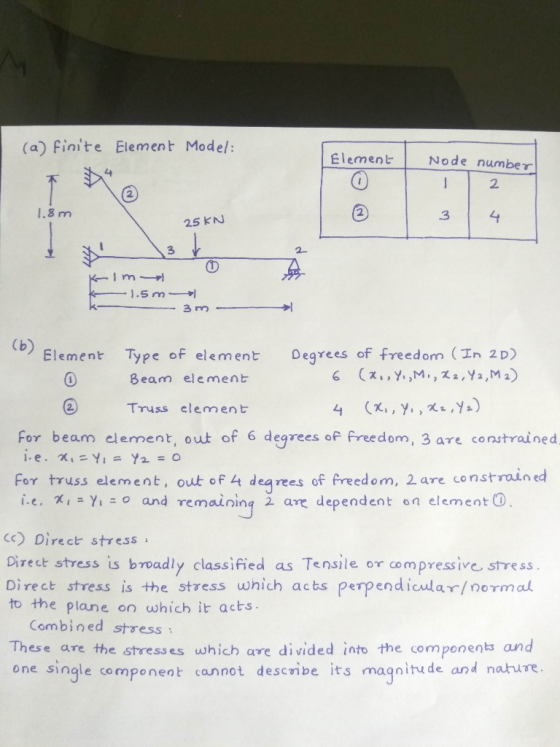
 QUESTION 2 21 Finite elements can appear in many forms such as two-dimensional and three- dimensional domains Give two examples and a sketch for each domain. (4) 22 Explain the following terms as used in Finite element equations a Plain stress b Plain strain 23 Use the Finite element method to develop the stiffness matrix for element 2 of the steel cantilever beam structure shown in Figure 2 The elastic modulus IS 200 kN/mm2 with a thickness of 1 unit...
finite element method OP QUESTION 1 (20 Marks) Calculation question (a)In a thin loaded plate shown...
 finite element method
OP QUESTION 1 (20 Marks) Calculation question (a)In a thin loaded plate shown in Figure 1, an area originally bounded by ABCD deformed to A', B', C' and D' upon loading. Estimate the strains,Exx, Eyy and Ey, and stresses, ox, Oyy and oxy of the element. Given that: E= 200 GPa and v 0.28. (10 Marks) All units are in mm Y 1 C (0,008,1.002) D 1,1) ko,1) B (1.005,0.002) A' (0.002,0.001) A X (0,0) (1,0) Figure...
finite element method
OP QUESTION 1 (20 Marks) Calculation question (a)In a thin loaded plate shown in Figure 1, an area originally bounded by ABCD deformed to A', B', C' and D' upon loading. Estimate the strains,Exx, Eyy and Ey, and stresses, ox, Oyy and oxy of the element. Given that: E= 200 GPa and v 0.28. (10 Marks) All units are in mm Y 1 C (0,008,1.002) D 1,1) ko,1) B (1.005,0.002) A' (0.002,0.001) A X (0,0) (1,0) Figure...
PLEASE WRITE/PRINT CLEARLY PLEASE SOLVE USING THE FINITE ELEMENT METHOD WHICH INCLUDES THE MATRIXES 2. The...
 PLEASE WRITE/PRINT CLEARLY PLEASE SOLVE USING THE FINITE ELEMENT
METHOD WHICH INCLUDES THE MATRIXES
2. The flow rate at node 1 is 0.16 liter/s (0.16 *10 m/s). The pressure at node 4 is 0 Pa (g). For the given conditions, the flow is laminar throughout the system. Using hand calculation determine i. The pressure in each node. ii. Flow in each element iii. Verify your results (25 + 10 + 5 = 40) (1) L= 10 m D-20 mm [2]...
PLEASE WRITE/PRINT CLEARLY PLEASE SOLVE USING THE FINITE ELEMENT
METHOD WHICH INCLUDES THE MATRIXES
2. The flow rate at node 1 is 0.16 liter/s (0.16 *10 m/s). The pressure at node 4 is 0 Pa (g). For the given conditions, the flow is laminar throughout the system. Using hand calculation determine i. The pressure in each node. ii. Flow in each element iii. Verify your results (25 + 10 + 5 = 40) (1) L= 10 m D-20 mm [2]...
PLEASE WRITE/PRINT CLEARLY AND SOLVE USING THE FINITE ELEMENT METHOD UNCLUDING MATRICIES 2. The flow rate...
 PLEASE WRITE/PRINT CLEARLY AND SOLVE USING THE FINITE ELEMENT
METHOD UNCLUDING MATRICIES
2. The flow rate at node 1 is 0.16 liter/s (0.16 *10-2 m/s). The pressure at node 4 is 0 Pa (g). For the given conditions, the flow is laminar throughout the system. Using hand calculation determine i. The pressure in each node. ii. Flow in each element iii. Verify your results (25 + 10 + 5 = 40) (1) L=10 m D=20 mm u = 8 x...
PLEASE WRITE/PRINT CLEARLY AND SOLVE USING THE FINITE ELEMENT
METHOD UNCLUDING MATRICIES
2. The flow rate at node 1 is 0.16 liter/s (0.16 *10-2 m/s). The pressure at node 4 is 0 Pa (g). For the given conditions, the flow is laminar throughout the system. Using hand calculation determine i. The pressure in each node. ii. Flow in each element iii. Verify your results (25 + 10 + 5 = 40) (1) L=10 m D=20 mm u = 8 x...
Question 2 20 points Save Answer A T shaped steel beam is used to support the...
 Question 2 20 points Save Answer A T shaped steel beam is used to support the loads shown below. The dimensions from the top and bottom of the shape to the centroid axis are shown on the sketch of the cross section and 1 x 106 mm4. Determine the magnitude of the maximum bending stress in MPa 15 KN 20 kN/m 60.7 mm OkNm 64.3 mm WT230-26
structural analysis Figure Q() Question 2 For the bar assemblages shown in Figure Q(2), determine the nodal displacements, the forces in each element and the reactions. Use the direct stiffness me...
 structural analysis
Figure Q() Question 2 For the bar assemblages shown in Figure Q(2), determine the nodal displacements, the forces in each element and the reactions. Use the direct stiffness method (25 marks) 35 kN E-210 GPa 2 A4 x 10m2 1 m im
Figure Q() Question 2 For the bar assemblages shown in Figure Q(2), determine the nodal displacements, the forces in each element and the reactions. Use the direct stiffness method (25 marks) 35 kN E-210 GPa 2...
structural analysis
Figure Q() Question 2 For the bar assemblages shown in Figure Q(2), determine the nodal displacements, the forces in each element and the reactions. Use the direct stiffness method (25 marks) 35 kN E-210 GPa 2 A4 x 10m2 1 m im
Figure Q() Question 2 For the bar assemblages shown in Figure Q(2), determine the nodal displacements, the forces in each element and the reactions. Use the direct stiffness method (25 marks) 35 kN E-210 GPa 2...
Need a solution for slope-deflection method Question 2 (20 marks) Use the Slope-Deflection Method to analyse...
 Need a solution for slope-deflection method
Question 2 (20 marks) Use the Slope-Deflection Method to analyse the frame in Figure 2. Plot diagrams for internal forces (M, V and N). Indicate magnitudes at all significant points. The bending stiffness of members is indicated in the figure. Neglect the effect of shear and axial forces on the structural deformations. 90 kNm 24 kN/m B v 64 kN a, 4m 2m ទឹក 9m Sm A 2ET ZEL 201 6m E] &m E1...
Need a solution for slope-deflection method
Question 2 (20 marks) Use the Slope-Deflection Method to analyse the frame in Figure 2. Plot diagrams for internal forces (M, V and N). Indicate magnitudes at all significant points. The bending stiffness of members is indicated in the figure. Neglect the effect of shear and axial forces on the structural deformations. 90 kNm 24 kN/m B v 64 kN a, 4m 2m ទឹក 9m Sm A 2ET ZEL 201 6m E] &m E1...
Name 1Pag Question 1 (35 marks) Use the method of virtual work to determine the vertical displace...
 structure design
Name 1Pag Question 1 (35 marks) Use the method of virtual work to determine the vertical displacement of joint C of the truss below The cross-sectional area of each member is A 300 mm2 and E- 200 GPa Note 1 GPa -1.0 x 10 kN/m 1 mm2-10 x 10-*m2 3 kN 2 m 2 m 1.5 m EA Set out wour computations as follows (a) Find the reactions at hinge support E and at roller support A b)...
structure design
Name 1Pag Question 1 (35 marks) Use the method of virtual work to determine the vertical displacement of joint C of the truss below The cross-sectional area of each member is A 300 mm2 and E- 200 GPa Note 1 GPa -1.0 x 10 kN/m 1 mm2-10 x 10-*m2 3 kN 2 m 2 m 1.5 m EA Set out wour computations as follows (a) Find the reactions at hinge support E and at roller support A b)...
 finite element method
.'ו Optus 11:56 AM Expert Q&A Finite element method QUESTION 4(20 Marks) - concept and calculation question Consider axial vibration of the circular steel bar shown in Figure 4. The steel bar properties are: p- 7800 kg/m and E-200 GPa. (a)lf the first two natural frequencies are required, sketch the finite element model with clearly labelled element numbers and node numbers, State the element types and the degree of freedoms solved (5 Marks (b)Calculate the stiffiness and...
finite element method
.'ו Optus 11:56 AM Expert Q&A Finite element method QUESTION 4(20 Marks) - concept and calculation question Consider axial vibration of the circular steel bar shown in Figure 4. The steel bar properties are: p- 7800 kg/m and E-200 GPa. (a)lf the first two natural frequencies are required, sketch the finite element model with clearly labelled element numbers and node numbers, State the element types and the degree of freedoms solved (5 Marks (b)Calculate the stiffiness and...
 Finite element method
Question 3 (10 marks) A shaft is to be modelled by finite element method. Describe an appropriate type of element that can be used to analyse the shaft. What is the minimum number of elements that must be used? Sketch the finite element model annotated with numbered nodes and numbered elements, and clearly show the degree of freedoms. Material: steel, Esteel | 3000 N 4.x=뉴94= 1.25x10% mm? 150 mm75 mm125 mm
Question 3 (10 marks) A shaft...
Finite element method
Question 3 (10 marks) A shaft is to be modelled by finite element method. Describe an appropriate type of element that can be used to analyse the shaft. What is the minimum number of elements that must be used? Sketch the finite element model annotated with numbered nodes and numbered elements, and clearly show the degree of freedoms. Material: steel, Esteel | 3000 N 4.x=뉴94= 1.25x10% mm? 150 mm75 mm125 mm
Question 3 (10 marks) A shaft...
 QUESTION 2 21 Finite elements can appear in many forms such as two-dimensional and three- dimensional domains Give two examples and a sketch for each domain. (4) 22 Explain the following terms as used in Finite element equations a Plain stress b Plain strain 23 Use the Finite element method to develop the stiffness matrix for element 2 of the steel cantilever beam structure shown in Figure 2 The elastic modulus IS 200 kN/mm2 with a thickness of 1 unit...
 finite element method
OP QUESTION 1 (20 Marks) Calculation question (a)In a thin loaded plate shown in Figure 1, an area originally bounded by ABCD deformed to A', B', C' and D' upon loading. Estimate the strains,Exx, Eyy and Ey, and stresses, ox, Oyy and oxy of the element. Given that: E= 200 GPa and v 0.28. (10 Marks) All units are in mm Y 1 C (0,008,1.002) D 1,1) ko,1) B (1.005,0.002) A' (0.002,0.001) A X (0,0) (1,0) Figure...
finite element method
OP QUESTION 1 (20 Marks) Calculation question (a)In a thin loaded plate shown in Figure 1, an area originally bounded by ABCD deformed to A', B', C' and D' upon loading. Estimate the strains,Exx, Eyy and Ey, and stresses, ox, Oyy and oxy of the element. Given that: E= 200 GPa and v 0.28. (10 Marks) All units are in mm Y 1 C (0,008,1.002) D 1,1) ko,1) B (1.005,0.002) A' (0.002,0.001) A X (0,0) (1,0) Figure...
 PLEASE WRITE/PRINT CLEARLY PLEASE SOLVE USING THE FINITE ELEMENT
METHOD WHICH INCLUDES THE MATRIXES
2. The flow rate at node 1 is 0.16 liter/s (0.16 *10 m/s). The pressure at node 4 is 0 Pa (g). For the given conditions, the flow is laminar throughout the system. Using hand calculation determine i. The pressure in each node. ii. Flow in each element iii. Verify your results (25 + 10 + 5 = 40) (1) L= 10 m D-20 mm [2]...
PLEASE WRITE/PRINT CLEARLY PLEASE SOLVE USING THE FINITE ELEMENT
METHOD WHICH INCLUDES THE MATRIXES
2. The flow rate at node 1 is 0.16 liter/s (0.16 *10 m/s). The pressure at node 4 is 0 Pa (g). For the given conditions, the flow is laminar throughout the system. Using hand calculation determine i. The pressure in each node. ii. Flow in each element iii. Verify your results (25 + 10 + 5 = 40) (1) L= 10 m D-20 mm [2]...
 PLEASE WRITE/PRINT CLEARLY AND SOLVE USING THE FINITE ELEMENT
METHOD UNCLUDING MATRICIES
2. The flow rate at node 1 is 0.16 liter/s (0.16 *10-2 m/s). The pressure at node 4 is 0 Pa (g). For the given conditions, the flow is laminar throughout the system. Using hand calculation determine i. The pressure in each node. ii. Flow in each element iii. Verify your results (25 + 10 + 5 = 40) (1) L=10 m D=20 mm u = 8 x...
PLEASE WRITE/PRINT CLEARLY AND SOLVE USING THE FINITE ELEMENT
METHOD UNCLUDING MATRICIES
2. The flow rate at node 1 is 0.16 liter/s (0.16 *10-2 m/s). The pressure at node 4 is 0 Pa (g). For the given conditions, the flow is laminar throughout the system. Using hand calculation determine i. The pressure in each node. ii. Flow in each element iii. Verify your results (25 + 10 + 5 = 40) (1) L=10 m D=20 mm u = 8 x...
 Question 2 20 points Save Answer A T shaped steel beam is used to support the loads shown below. The dimensions from the top and bottom of the shape to the centroid axis are shown on the sketch of the cross section and 1 x 106 mm4. Determine the magnitude of the maximum bending stress in MPa 15 KN 20 kN/m 60.7 mm OkNm 64.3 mm WT230-26
 structural analysis
Figure Q() Question 2 For the bar assemblages shown in Figure Q(2), determine the nodal displacements, the forces in each element and the reactions. Use the direct stiffness method (25 marks) 35 kN E-210 GPa 2 A4 x 10m2 1 m im
Figure Q() Question 2 For the bar assemblages shown in Figure Q(2), determine the nodal displacements, the forces in each element and the reactions. Use the direct stiffness method (25 marks) 35 kN E-210 GPa 2...
structural analysis
Figure Q() Question 2 For the bar assemblages shown in Figure Q(2), determine the nodal displacements, the forces in each element and the reactions. Use the direct stiffness method (25 marks) 35 kN E-210 GPa 2 A4 x 10m2 1 m im
Figure Q() Question 2 For the bar assemblages shown in Figure Q(2), determine the nodal displacements, the forces in each element and the reactions. Use the direct stiffness method (25 marks) 35 kN E-210 GPa 2...
 Need a solution for slope-deflection method
Question 2 (20 marks) Use the Slope-Deflection Method to analyse the frame in Figure 2. Plot diagrams for internal forces (M, V and N). Indicate magnitudes at all significant points. The bending stiffness of members is indicated in the figure. Neglect the effect of shear and axial forces on the structural deformations. 90 kNm 24 kN/m B v 64 kN a, 4m 2m ទឹក 9m Sm A 2ET ZEL 201 6m E] &m E1...
Need a solution for slope-deflection method
Question 2 (20 marks) Use the Slope-Deflection Method to analyse the frame in Figure 2. Plot diagrams for internal forces (M, V and N). Indicate magnitudes at all significant points. The bending stiffness of members is indicated in the figure. Neglect the effect of shear and axial forces on the structural deformations. 90 kNm 24 kN/m B v 64 kN a, 4m 2m ទឹក 9m Sm A 2ET ZEL 201 6m E] &m E1...
 structure design
Name 1Pag Question 1 (35 marks) Use the method of virtual work to determine the vertical displacement of joint C of the truss below The cross-sectional area of each member is A 300 mm2 and E- 200 GPa Note 1 GPa -1.0 x 10 kN/m 1 mm2-10 x 10-*m2 3 kN 2 m 2 m 1.5 m EA Set out wour computations as follows (a) Find the reactions at hinge support E and at roller support A b)...
structure design
Name 1Pag Question 1 (35 marks) Use the method of virtual work to determine the vertical displacement of joint C of the truss below The cross-sectional area of each member is A 300 mm2 and E- 200 GPa Note 1 GPa -1.0 x 10 kN/m 1 mm2-10 x 10-*m2 3 kN 2 m 2 m 1.5 m EA Set out wour computations as follows (a) Find the reactions at hinge support E and at roller support A b)...
Most questions answered within 3 hours.
-
Although Epicurus advocates pursuing pleasure for the
good life, discuss a few reasons why he does...
asked 12 minutes ago -
Problem 1: Present entries to record the selected transactions
described below:
(a)
Issued $2,790,000 of 5-year,...
asked 19 minutes ago -
Using technology to support HR activities increases:
a.
the efficiency of the administrative HR functions.
b....
asked 20 minutes ago -
1. List the features used to classify leaf
types.
2. List some characteristics that are shared...
asked 25 minutes ago -
The three elements of Value Proposition, Key Customers, and
Capabilities operate within an environment. Which of...
asked 27 minutes ago -
Katelynn, a physician, earns $200,000 from her medical practice
in the current year. She receives $45,000...
asked 35 minutes ago -
Each row of the table below describes an aqueous solution at
25°C
.
The second column...
asked 39 minutes ago -
A horizontal wire is at y = 0. Current travels in the +x
direction. The magnetic...
asked 39 minutes ago -
Let X be a continuous random variable whose PDF is Let X be a
continuous random...
asked 1 hour ago -
Martinez Company’s relevant range of production is 7,500 units
to 12,500 units. When it produces and...
asked 58 minutes ago -
A football with a mass of 1.2 kg is kicked from ground level to
a height...
asked 1 hour ago -
Remember: Changes in supply determinants shift supply, and
changes in demand determinants shift demand. We say...
asked 1 hour ago