
Homework Answers
matlab code:
t=0:0.001:10;
f=3*exp(-3*t)+5*exp(-2*t)+exp(-t).*(4*cos(3*t)+6*sin(3*t))+exp(-4*t);
figure
plot(t,f),grid on
r=[3;5;2;2;-3*i;3*i;1];
p=[-3;-2;-1+3*i;-1-3*i;-1+3*i;-1-3*i;-4];
k=[];
[b a]=residue(r,p,k)
sys=tf(b,a)
figure
pzmap(sys)
p=pole(sys)
z=zero(sys)
figure
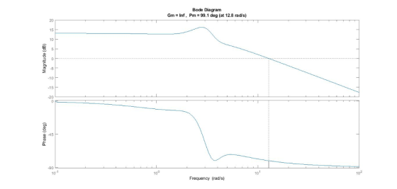
bode(sys)
margin(sys)
output:
b =
13 142 834 3352 8536 13392 10824
a =
1 13 86 384 1180 2516 3560 2400
sys =
13 s^6 + 142 s^5 + 834 s^4 + 3352 s^3 + 8536 s^2 + 13392 s +
10824
---------------------------------------------------------------------
s^7 + 13 s^6 + 86 s^5 + 384 s^4 + 1180 s^3 + 2516 s^2 + 3560 s +
2400
Continuous-time transfer function.
p =
-1.0000 + 3.0000i
-1.0000 - 3.0000i
-1.0000 + 3.0000i
-1.0000 - 3.0000i
-4.0000 + 0.0000i
-3.0000 + 0.0000i
-2.0000 + 0.0000i
z =
-0.9147 + 3.7651i
-0.9147 - 3.7651i
-3.8609 + 0.0000i
-2.6326 + 0.0000i
-1.3001 + 1.9407i
-1.3001 - 1.9407i
impulse responce:

p-z map:
 bode plot:
Add Answer to:
Problem 1: The impulse response ht) for a particular LTI system is shown below hit) Be5e (4 cos(3...
Problem 3 (30 points) An LTI system has an impulse response hin], whose z-transform equals 1-1...
 Problem 3 (30 points) An LTI system has an impulse response hin], whose z-transform equals 1-1 1. List all the poles and zeros of H(2). Sketch the pole-zero plot.. 2. If this system is causal, provide the ROC of H(2) and the expression of hin. case, is this system also stable? 3. If the ROC of H(z) does not exist, provide and the expression of hn.
BC:9.4 A LTI discrete time system has an impulse response h[n] = (−0.6)nu[n] + (0.95)nu[n −...
 BC:9.4 A LTI discrete time system has an impulse response h[n] =
(−0.6)nu[n] + (0.95)nu[n − 1] Find the transfer function, Hˆ (e jωˆ
), in the normalized frequency domain. Use Matlab to plot the
magnitude and phase (in degrees) of Hˆ (e jωˆ ) in the range of −π
≤ ωˆ ≤ π. Attach your Matlab source code with the plots.
BC:9.4 A LTI discrete time system has an impulse response h[n] = (-0.6)"u[n] + (0.95)"u[n-1] Find the transfer...
BC:9.4 A LTI discrete time system has an impulse response h[n] =
(−0.6)nu[n] + (0.95)nu[n − 1] Find the transfer function, Hˆ (e jωˆ
), in the normalized frequency domain. Use Matlab to plot the
magnitude and phase (in degrees) of Hˆ (e jωˆ ) in the range of −π
≤ ωˆ ≤ π. Attach your Matlab source code with the plots.
BC:9.4 A LTI discrete time system has an impulse response h[n] = (-0.6)"u[n] + (0.95)"u[n-1] Find the transfer...
Suppose that for the LTI system depicted in the following figure (a), the impulse response and th...
 Suppose that for the LTI system depicted in the following figure (a), the impulse response and the transfer function are given by h(t) = e-tu(t) H(S) = s+1 1 H 100 The input signal x(t) is the square wave of Figure (b), where t is in seconds. Since the fundamental period is To = 2π, the fundamental frequency is ao-2π/L = 1 rad/s and kaa-k. 3t (a) Use the Table provided to find the exponential Fourier series of the signal...
(1) For the impulse response (h(t)) and input signal (x(t)) of an LTI system shown below,...
 (1) For the impulse response (h(t)) and input signal (x(t)) of an LTI system shown below, find and plot the output response (y(t)) by integrating the convolution analytically h(t) x(t) t (s)
Plz explain all steps. Make it as simple as possible. Thx! An LTI system has impulse response h(n) - sin (a) Find a difference equation (with real coefficients) to implement the system. Show your wor...
 Plz explain all steps. Make it as simple as possible. Thx!
An LTI system has impulse response h(n) - sin (a) Find a difference equation (with real coefficients) to implement the system. Show your work. (b) Find and sketch the poles and zeros of the system
An LTI system has impulse response h(n) - sin (a) Find a difference equation (with real coefficients) to implement the system. Show your work. (b) Find and sketch the poles and zeros of the...
Plz explain all steps. Make it as simple as possible. Thx!
An LTI system has impulse response h(n) - sin (a) Find a difference equation (with real coefficients) to implement the system. Show your work. (b) Find and sketch the poles and zeros of the system
An LTI system has impulse response h(n) - sin (a) Find a difference equation (with real coefficients) to implement the system. Show your work. (b) Find and sketch the poles and zeros of the...
BC:9.4 A LTI discrete time system has an impulse response h[n] = (-0.8)"u[n] + (0.65)"u[n-1] Find...
 BC:9.4 A LTI discrete time system has an impulse response h[n] = (-0.8)"u[n] + (0.65)"u[n-1] Find the transfer function, #(eo), in the normalized frequency domain. Use Matlab to plot the magni- tude and phase (in degrees) of H(eo) in the range of-? < ? < ?. Attach your Matlab source code with the plots. 1212 AM ^???4/4/2013
Consider an LTI system with the impulse response h(t) = e- . Is the system casual?...
 Consider an LTI system with the impulse response h(t) = e- . Is the system casual? Explain. Find and plot the output s(t) given that the system input is x(t) = u(t). Note that s(t) in this case is commonly known as the step response of the system. If the input is x(t) = u(t)-u(t-T). Express the output y(t) as a function of s(t). Also, explicitly write the output y(t) as a function of t. a) b) c)
A continuous-time LTI system has unit impulse response h(t). The Laplace transform of h(t), also called...
 A continuous-time LTI system has unit impulse response h(t). The
Laplace transform of h(t), also called the “transfer function” of
the LTI system, is
.
For each of the following cases, determine the region of
convergence (ROC) for H(s) and the corresponding h(t), and
determine whether the Fourier transform of h(t) exists.
(a) The LTI system is causal but not stable.
(b) The LTI system is stable but not causal.
(c) The LTI system is neither stable nor causal
8...
A continuous-time LTI system has unit impulse response h(t). The
Laplace transform of h(t), also called the “transfer function” of
the LTI system, is
.
For each of the following cases, determine the region of
convergence (ROC) for H(s) and the corresponding h(t), and
determine whether the Fourier transform of h(t) exists.
(a) The LTI system is causal but not stable.
(b) The LTI system is stable but not causal.
(c) The LTI system is neither stable nor causal
8...
ECE 202 Lab 5 Poles & Zeros, Impulse Response II Prelab 1. Assuming the initial conditions...
 ECE 202 Lab 5 Poles & Zeros, Impulse Response II Prelab 1. Assuming the initial conditions are zero, determine the transfer function H(s), for the circuit shown below. Also, inverse transform the transfer function to obtain the impulse response for the circuit, h() IN(S) 100? 1mH V out IN 0.01 ?F 2 What values of corespon o the poles and aeros df H)7 What yoe of signal will produce zero steady state output? constant) for this circuit? produce a zero...
alpha = 5.0 beta = 7.1 zeta = 6.9 PROBLEM 1 (20 points). Given the filter with transfer function +28-1+-2 11(2) = 1-(α/10)2-4 (a2/100):-2 Use MATLAB to Find the zeros and poles of H() Plot the pole...
 alpha = 5.0
beta = 7.1
zeta = 6.9
PROBLEM 1 (20 points). Given the filter with transfer function +28-1+-2 11(2) = 1-(α/10)2-4 (a2/100):-2 Use MATLAB to Find the zeros and poles of H() Plot the poles and zeros on the -plane. The pot should include the uit circle. Plot the magnitude response (in dB) Plot the phase response. Deliverables: Your MATLAB code used to solve Problem 1 and all the generated plots.
PROBLEM 1 (20 points). Given the filter...
alpha = 5.0
beta = 7.1
zeta = 6.9
PROBLEM 1 (20 points). Given the filter with transfer function +28-1+-2 11(2) = 1-(α/10)2-4 (a2/100):-2 Use MATLAB to Find the zeros and poles of H() Plot the poles and zeros on the -plane. The pot should include the uit circle. Plot the magnitude response (in dB) Plot the phase response. Deliverables: Your MATLAB code used to solve Problem 1 and all the generated plots.
PROBLEM 1 (20 points). Given the filter...
 Problem 3 (30 points) An LTI system has an impulse response hin], whose z-transform equals 1-1 1. List all the poles and zeros of H(2). Sketch the pole-zero plot.. 2. If this system is causal, provide the ROC of H(2) and the expression of hin. case, is this system also stable? 3. If the ROC of H(z) does not exist, provide and the expression of hn.
 BC:9.4 A LTI discrete time system has an impulse response h[n] =
(−0.6)nu[n] + (0.95)nu[n − 1] Find the transfer function, Hˆ (e jωˆ
), in the normalized frequency domain. Use Matlab to plot the
magnitude and phase (in degrees) of Hˆ (e jωˆ ) in the range of −π
≤ ωˆ ≤ π. Attach your Matlab source code with the plots.
BC:9.4 A LTI discrete time system has an impulse response h[n] = (-0.6)"u[n] + (0.95)"u[n-1] Find the transfer...
BC:9.4 A LTI discrete time system has an impulse response h[n] =
(−0.6)nu[n] + (0.95)nu[n − 1] Find the transfer function, Hˆ (e jωˆ
), in the normalized frequency domain. Use Matlab to plot the
magnitude and phase (in degrees) of Hˆ (e jωˆ ) in the range of −π
≤ ωˆ ≤ π. Attach your Matlab source code with the plots.
BC:9.4 A LTI discrete time system has an impulse response h[n] = (-0.6)"u[n] + (0.95)"u[n-1] Find the transfer...
 Suppose that for the LTI system depicted in the following figure (a), the impulse response and the transfer function are given by h(t) = e-tu(t) H(S) = s+1 1 H 100 The input signal x(t) is the square wave of Figure (b), where t is in seconds. Since the fundamental period is To = 2π, the fundamental frequency is ao-2π/L = 1 rad/s and kaa-k. 3t (a) Use the Table provided to find the exponential Fourier series of the signal...
 (1) For the impulse response (h(t)) and input signal (x(t)) of an LTI system shown below, find and plot the output response (y(t)) by integrating the convolution analytically h(t) x(t) t (s)
 Plz explain all steps. Make it as simple as possible. Thx!
An LTI system has impulse response h(n) - sin (a) Find a difference equation (with real coefficients) to implement the system. Show your work. (b) Find and sketch the poles and zeros of the system
An LTI system has impulse response h(n) - sin (a) Find a difference equation (with real coefficients) to implement the system. Show your work. (b) Find and sketch the poles and zeros of the...
Plz explain all steps. Make it as simple as possible. Thx!
An LTI system has impulse response h(n) - sin (a) Find a difference equation (with real coefficients) to implement the system. Show your work. (b) Find and sketch the poles and zeros of the system
An LTI system has impulse response h(n) - sin (a) Find a difference equation (with real coefficients) to implement the system. Show your work. (b) Find and sketch the poles and zeros of the...
 BC:9.4 A LTI discrete time system has an impulse response h[n] = (-0.8)"u[n] + (0.65)"u[n-1] Find the transfer function, #(eo), in the normalized frequency domain. Use Matlab to plot the magni- tude and phase (in degrees) of H(eo) in the range of-? < ? < ?. Attach your Matlab source code with the plots. 1212 AM ^???4/4/2013
 Consider an LTI system with the impulse response h(t) = e- . Is the system casual? Explain. Find and plot the output s(t) given that the system input is x(t) = u(t). Note that s(t) in this case is commonly known as the step response of the system. If the input is x(t) = u(t)-u(t-T). Express the output y(t) as a function of s(t). Also, explicitly write the output y(t) as a function of t. a) b) c)
 A continuous-time LTI system has unit impulse response h(t). The
Laplace transform of h(t), also called the “transfer function” of
the LTI system, is
.
For each of the following cases, determine the region of
convergence (ROC) for H(s) and the corresponding h(t), and
determine whether the Fourier transform of h(t) exists.
(a) The LTI system is causal but not stable.
(b) The LTI system is stable but not causal.
(c) The LTI system is neither stable nor causal
8...
A continuous-time LTI system has unit impulse response h(t). The
Laplace transform of h(t), also called the “transfer function” of
the LTI system, is
.
For each of the following cases, determine the region of
convergence (ROC) for H(s) and the corresponding h(t), and
determine whether the Fourier transform of h(t) exists.
(a) The LTI system is causal but not stable.
(b) The LTI system is stable but not causal.
(c) The LTI system is neither stable nor causal
8...
 ECE 202 Lab 5 Poles & Zeros, Impulse Response II Prelab 1. Assuming the initial conditions are zero, determine the transfer function H(s), for the circuit shown below. Also, inverse transform the transfer function to obtain the impulse response for the circuit, h() IN(S) 100? 1mH V out IN 0.01 ?F 2 What values of corespon o the poles and aeros df H)7 What yoe of signal will produce zero steady state output? constant) for this circuit? produce a zero...
 alpha = 5.0
beta = 7.1
zeta = 6.9
PROBLEM 1 (20 points). Given the filter with transfer function +28-1+-2 11(2) = 1-(α/10)2-4 (a2/100):-2 Use MATLAB to Find the zeros and poles of H() Plot the poles and zeros on the -plane. The pot should include the uit circle. Plot the magnitude response (in dB) Plot the phase response. Deliverables: Your MATLAB code used to solve Problem 1 and all the generated plots.
PROBLEM 1 (20 points). Given the filter...
alpha = 5.0
beta = 7.1
zeta = 6.9
PROBLEM 1 (20 points). Given the filter with transfer function +28-1+-2 11(2) = 1-(α/10)2-4 (a2/100):-2 Use MATLAB to Find the zeros and poles of H() Plot the poles and zeros on the -plane. The pot should include the uit circle. Plot the magnitude response (in dB) Plot the phase response. Deliverables: Your MATLAB code used to solve Problem 1 and all the generated plots.
PROBLEM 1 (20 points). Given the filter...
Most questions answered within 3 hours.
-
The mass structure of a spiral galaxy may be determined by
measurement of its___________ ________________
asked 3 minutes ago -
How do you define corrupt power? Lord Acton, a British historian
of the late 19th century,...
asked 1 minute ago -
1. If demand deceases and supply remains constant, what happens
to the market equilibrium?
A. Quantity...
asked 7 minutes ago -
A ball of mass 81 kg is dropped from a height of 22 m. What is...
asked 8 minutes ago -
There are 3 golden retrievers, 2 dachshunds, and 4 chocolate
labs in a kennel. Two dogs...
asked 24 minutes ago -
When a fixture of real property is physically detached from the
real property, it is known...
asked 22 minutes ago -
Imagine you are driving around a horizontal circular track (such
as a roundabout at an intersection...
asked 38 minutes ago -
Draw the structures that correspond to the following names.
Correct any names that are not in...
asked 46 minutes ago -
Do elephants and cows present an interesting dichotomy when
viewed from the perspective of property rights?
asked 58 minutes ago -
USE an API
You have a drop down list of 4 cities.
Upon selecting a particular...
asked 58 minutes ago -
Which type of chemical reaction is regulated by altering an
enzyme's function?
a.) irreversible
b.) reversible
asked 1 hour ago -
Supply management is a developing ____________ and an area of
management _______________.
1. discipline / responsibility...
asked 1 hour ago