
Homework Answers


Thank you
Add Answer to:
2 Comsider a DC motor, ts ampifier, losed loposition contrller and ld which is connected to the m...
control system System Description: The figure 1 and 2 below show, respectively, components and block diagram...
 control system
System Description: The figure 1 and 2 below show, respectively, components and block diagram of a motor and the measurements of velocity (via the tacho unit) and position (via the potentiometer). n represents the gearbox ratio between the rotating shaft and the output shaft. The left-hand side of the diagram represents the controller. A reference set point for the rotating shaft is entered in degrees and this is equivalent voltage. The error is calculated by subtracting the measured...
control system
System Description: The figure 1 and 2 below show, respectively, components and block diagram of a motor and the measurements of velocity (via the tacho unit) and position (via the potentiometer). n represents the gearbox ratio between the rotating shaft and the output shaft. The left-hand side of the diagram represents the controller. A reference set point for the rotating shaft is entered in degrees and this is equivalent voltage. The error is calculated by subtracting the measured...
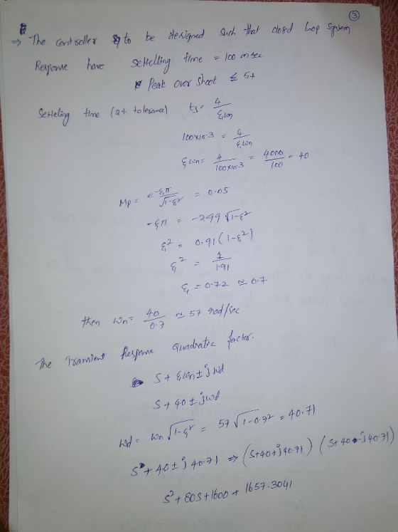
Problem 2: (20 points) A DC Motor with negligible armature inductance is used in a position...
 Problem 2: (20 points) A DC Motor with negligible armature inductance is used in a position control applications. The open-loop transfer function is 50 G(s) = s(s/5+1) Using a Bode Plot of the system and Frequency Domain Methods, design an analog compensator to meet the following specifications: The bandwidth of the compensated system is no less than that of the uncompensated system. • The step response overshoot is less than 20%. • The steady-state error to a unit-ramp input is...
2. The block diagram below model a simple DC motor for speed control application. Input V(s)...
 2. The block diagram below model a simple DC motor for speed control application. Input V(s) is the desired speed in voltage, and the output Y(s) is the actual speed. Tachogenerator, H, convert the actual speed to corresponding voltage. Amplifier Motor and gears X() 5 Ls +R Tachogenerator H The following parameters are known about the system: Amplifier gain: A=2; Motor inductance: L=5H Tachogenerator gain: H=0.15; Determine the following: The system transfer function The value of the motor resistance, R,...
Consider the DC motor-driven wheeled mobile robot shown in figure, in which m is the mass...
Consider the DC motor-driven wheeled mobile robot shown in figure, in which m is the mass of the wheeled mobile robot, r is the radius of the driving wheel, and T is the torque delivered to the wheeled mobile robot by the DC motor. For simplicity, the motion is restricted to one spatial dimension. The figure also shows the simplified drive system, including the equivalent electrical circuit of the DC motor, the gears, and the driving wheel. The motor parameter...
D.C. motor is shown below, where the inductance L and the resistance R model the armature circuit. The voltage Vbrepresents the back-emf which is proportional to dθ/dt via Kf. The torque T generated b...
 D.C. motor is shown below, where the inductance
L and the resistance R model the
armature circuit. The voltage
Vbrepresents the back-emf
which is proportional to dθ/dt via
Kf. The torque T
generated by the motor is proportional to the
i via a constant
Kt. In this application, let the
constants Kt =
Kf. The inertia
Jrepresents the combined inertia of the motor and
load. The viscous friction acting on the output shaft is
b. Attached to the shaft is...
D.C. motor is shown below, where the inductance
L and the resistance R model the
armature circuit. The voltage
Vbrepresents the back-emf
which is proportional to dθ/dt via
Kf. The torque T
generated by the motor is proportional to the
i via a constant
Kt. In this application, let the
constants Kt =
Kf. The inertia
Jrepresents the combined inertia of the motor and
load. The viscous friction acting on the output shaft is
b. Attached to the shaft is...
Consider the electromechanical dynamic system shown in Figure 1(a). It consists of a cart of mass...
 This assignment is for my Engr dynamics systems class.
Consider the electromechanical dynamic system shown in Figure 1(a). It consists of a cart of mass m moving without slipping on a linear ground track. The cart is equipped with an armature-controlled DC motor, which is coupled to a rack and pinion mechanism to convert the rotational motion to translation and to create the driving force for the system. Figure 1(b) shows the simplified equivalent electric circuit and the mechanical model...
This assignment is for my Engr dynamics systems class.
Consider the electromechanical dynamic system shown in Figure 1(a). It consists of a cart of mass m moving without slipping on a linear ground track. The cart is equipped with an armature-controlled DC motor, which is coupled to a rack and pinion mechanism to convert the rotational motion to translation and to create the driving force for the system. Figure 1(b) shows the simplified equivalent electric circuit and the mechanical model...
Laplace Analysis of the Permanent Magnet Brushed DC Motor and the right final answer should be...
 Laplace Analysis of the Permanent Magnet Brushed DC Motor
and the right final answer should be like this
A permanent magnet brushed DC motor (the type of motor that spins when connected to a constant voltage) can be described by the simplified model tö+) = Kv, where o is the angle of the motor shaft, v is the voltage applied to the motor, 7 is a positive constant known as the motor time constant, and K is a positive constant...
Laplace Analysis of the Permanent Magnet Brushed DC Motor
and the right final answer should be like this
A permanent magnet brushed DC motor (the type of motor that spins when connected to a constant voltage) can be described by the simplified model tö+) = Kv, where o is the angle of the motor shaft, v is the voltage applied to the motor, 7 is a positive constant known as the motor time constant, and K is a positive constant...
solve quastion 3,4 and 5 B. Tasks and Guide 1. System description and Mathematical modeling The...
 solve quastion 3,4 and 5
B. Tasks and Guide 1. System description and Mathematical modeling The antenna positioning system is shown in Fig. 1. In this problem we consider the yaw angle control system, where 0(t) is the yaw angle. Suppose that the gain of the power amplifier is 5 , and that the gear ratio and the angle sensor (the shaft encoder and the data hold) are such that (t)= 0.40(t) where the units of v,(t) are volts and...
solve quastion 3,4 and 5
B. Tasks and Guide 1. System description and Mathematical modeling The antenna positioning system is shown in Fig. 1. In this problem we consider the yaw angle control system, where 0(t) is the yaw angle. Suppose that the gain of the power amplifier is 5 , and that the gear ratio and the angle sensor (the shaft encoder and the data hold) are such that (t)= 0.40(t) where the units of v,(t) are volts and...
 control system
System Description: The figure 1 and 2 below show, respectively, components and block diagram of a motor and the measurements of velocity (via the tacho unit) and position (via the potentiometer). n represents the gearbox ratio between the rotating shaft and the output shaft. The left-hand side of the diagram represents the controller. A reference set point for the rotating shaft is entered in degrees and this is equivalent voltage. The error is calculated by subtracting the measured...
control system
System Description: The figure 1 and 2 below show, respectively, components and block diagram of a motor and the measurements of velocity (via the tacho unit) and position (via the potentiometer). n represents the gearbox ratio between the rotating shaft and the output shaft. The left-hand side of the diagram represents the controller. A reference set point for the rotating shaft is entered in degrees and this is equivalent voltage. The error is calculated by subtracting the measured...
 Problem 2: (20 points) A DC Motor with negligible armature inductance is used in a position control applications. The open-loop transfer function is 50 G(s) = s(s/5+1) Using a Bode Plot of the system and Frequency Domain Methods, design an analog compensator to meet the following specifications: The bandwidth of the compensated system is no less than that of the uncompensated system. • The step response overshoot is less than 20%. • The steady-state error to a unit-ramp input is...
 2. The block diagram below model a simple DC motor for speed control application. Input V(s) is the desired speed in voltage, and the output Y(s) is the actual speed. Tachogenerator, H, convert the actual speed to corresponding voltage. Amplifier Motor and gears X() 5 Ls +R Tachogenerator H The following parameters are known about the system: Amplifier gain: A=2; Motor inductance: L=5H Tachogenerator gain: H=0.15; Determine the following: The system transfer function The value of the motor resistance, R,...
 D.C. motor is shown below, where the inductance
L and the resistance R model the
armature circuit. The voltage
Vbrepresents the back-emf
which is proportional to dθ/dt via
Kf. The torque T
generated by the motor is proportional to the
i via a constant
Kt. In this application, let the
constants Kt =
Kf. The inertia
Jrepresents the combined inertia of the motor and
load. The viscous friction acting on the output shaft is
b. Attached to the shaft is...
D.C. motor is shown below, where the inductance
L and the resistance R model the
armature circuit. The voltage
Vbrepresents the back-emf
which is proportional to dθ/dt via
Kf. The torque T
generated by the motor is proportional to the
i via a constant
Kt. In this application, let the
constants Kt =
Kf. The inertia
Jrepresents the combined inertia of the motor and
load. The viscous friction acting on the output shaft is
b. Attached to the shaft is...
 This assignment is for my Engr dynamics systems class.
Consider the electromechanical dynamic system shown in Figure 1(a). It consists of a cart of mass m moving without slipping on a linear ground track. The cart is equipped with an armature-controlled DC motor, which is coupled to a rack and pinion mechanism to convert the rotational motion to translation and to create the driving force for the system. Figure 1(b) shows the simplified equivalent electric circuit and the mechanical model...
This assignment is for my Engr dynamics systems class.
Consider the electromechanical dynamic system shown in Figure 1(a). It consists of a cart of mass m moving without slipping on a linear ground track. The cart is equipped with an armature-controlled DC motor, which is coupled to a rack and pinion mechanism to convert the rotational motion to translation and to create the driving force for the system. Figure 1(b) shows the simplified equivalent electric circuit and the mechanical model...
 Laplace Analysis of the Permanent Magnet Brushed DC Motor
and the right final answer should be like this
A permanent magnet brushed DC motor (the type of motor that spins when connected to a constant voltage) can be described by the simplified model tö+) = Kv, where o is the angle of the motor shaft, v is the voltage applied to the motor, 7 is a positive constant known as the motor time constant, and K is a positive constant...
Laplace Analysis of the Permanent Magnet Brushed DC Motor
and the right final answer should be like this
A permanent magnet brushed DC motor (the type of motor that spins when connected to a constant voltage) can be described by the simplified model tö+) = Kv, where o is the angle of the motor shaft, v is the voltage applied to the motor, 7 is a positive constant known as the motor time constant, and K is a positive constant...
 solve quastion 3,4 and 5
B. Tasks and Guide 1. System description and Mathematical modeling The antenna positioning system is shown in Fig. 1. In this problem we consider the yaw angle control system, where 0(t) is the yaw angle. Suppose that the gain of the power amplifier is 5 , and that the gear ratio and the angle sensor (the shaft encoder and the data hold) are such that (t)= 0.40(t) where the units of v,(t) are volts and...
solve quastion 3,4 and 5
B. Tasks and Guide 1. System description and Mathematical modeling The antenna positioning system is shown in Fig. 1. In this problem we consider the yaw angle control system, where 0(t) is the yaw angle. Suppose that the gain of the power amplifier is 5 , and that the gear ratio and the angle sensor (the shaft encoder and the data hold) are such that (t)= 0.40(t) where the units of v,(t) are volts and...
Most questions answered within 3 hours.
-
Hello! I was wondering if I could have some help?
If the vapor pressure of carvone...
asked 7 minutes ago -
An economist wants to estimate the mean per capita income (in
thousands of dollars) for a...
asked 26 minutes ago -
What would be the input/output characteristic of a circuit
obtained by putting two of your 2's-complementers...
asked 25 minutes ago -
In Drosophila, the transition from the syncytial blastoderm
stage to the cellular blastoderm stage is a...
asked 54 minutes ago -
Project management question:
Name 3 different types of resources (hint: humans are one
type)
asked 1 hour ago -
Consider the following reaction: C 2H 2( g) + 2H 2( g) C 2H 6(
g)...
asked 1 hour ago -
Consider a 1.0 L buffer containing 0.092 mol L-1 HCOOH and 0.100
mol L-1 HCOO-. What...
asked 1 hour ago -
Koch Realty has owned a vacant land with a FMV of
$775,000 and an adjusted basis...
asked 1 hour ago -
It is estimated 29% of all adults in United States invest in
stocks and that 85%...
asked 1 hour ago -
What does a 2-sided p value of 0.04 mean? (I am not asking if it
is...
asked 1 hour ago -
A parallel-plate capacitor is made from two aluminum-foil
sheets, each 7.8 cmcm wide and 5.1 mmlong....
asked 1 hour ago -
1. why is toluene a stronger nucleophile than benzene?
2.why is phenol a stronger nucleophile than...
asked 2 hours ago