
Homework Answers


![Write the MATLAB code for compensated system. num1=[250] den=conv([1].[15]); sys1=tf(num1, dent); num2=10*[1 201 den2= [1 200](http://img.homeworklib.com/questions/0411e310-de96-11ea-9d78-f9b71887850b.png?x-oss-process=image/resize,w_560)

Add Answer to:
Problem 2: (20 points) A DC Motor with negligible armature inductance is used in a position...
Problem 1: (20 points) Assume that a standard unity feedback system has the open- loop plant...
 Problem 1: (20 points) Assume that a standard unity feedback system has the open- loop plant transfer function: G(S) s(s+3)(s +6) Use Root Locus Methods to design an analog compensator to meet the following specifications: • The step response settling time is less than 5 seconds. • The step response overshoot is less than 17%. • The steady-state error to a unit-ramp input is less than 10%.
onsider a DC electric motor. Assume the armature inductance is negligible. Consider the harmature voltage ea...
 onsider a DC electric motor. Assume the armature inductance is negligible. Consider the harmature voltage ea as the input and the angular displacement @t) as the ulput. By measuring an input and the system's response as functions of time, the transfer function is then found to be 10s(s +1) What are the motor time-constant and the motor gain? a. b. iIt the input is 2 u(l), find the output i.e. the angular displacement et) c. Find the angular speed o(t)
2. You are given the motor whose transfer function is shown in Figure 2(a). s) e(s) Amplifier Mot...
 Control system
2. You are given the motor whose transfer function is shown in Figure 2(a). s) e(s) Amplifier Motor C(s) 15 Tachometer Кр Figure 2 a) If this motor were the forward transfer function of a unity feedback system, calculate the percent overshoot and settling time that could be expected. b) You want to improve the closed-loop response. Since the motor constants cannot be changed and you cannot use a different motor, an amplifier and tachometer are inserted into...
Control system
2. You are given the motor whose transfer function is shown in Figure 2(a). s) e(s) Amplifier Motor C(s) 15 Tachometer Кр Figure 2 a) If this motor were the forward transfer function of a unity feedback system, calculate the percent overshoot and settling time that could be expected. b) You want to improve the closed-loop response. Since the motor constants cannot be changed and you cannot use a different motor, an amplifier and tachometer are inserted into...
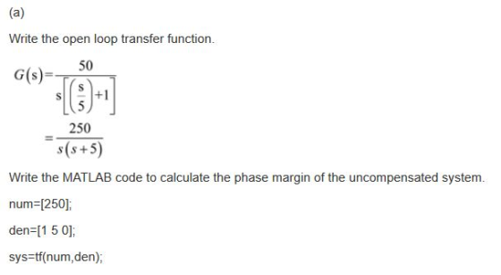
Q.4 A position control system is shown in Figure Q4. Assume that K(s) = K, the plant 50 s(0.2s +1) transfer function is given by G(s) s02s y(t) r(t) Figure Q4: Feedback control system. (a) Design a l...
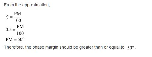
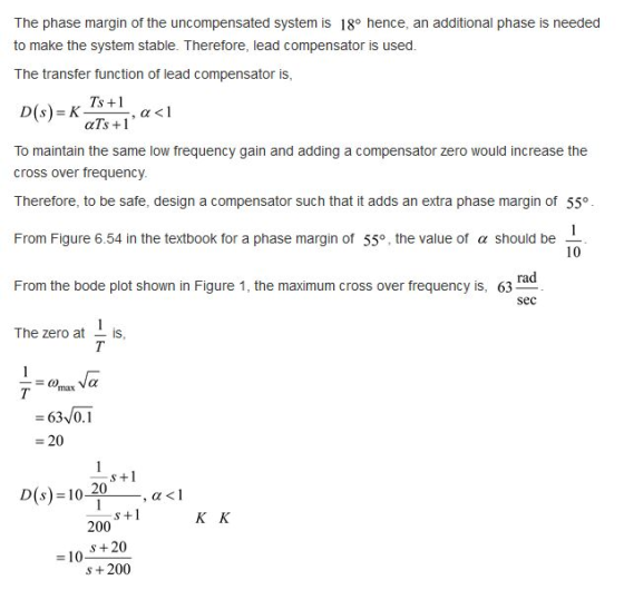
 Q.4 A position control system is shown in Figure Q4. Assume that K(s) = K, the plant 50 s(0.2s +1) transfer function is given by G(s) s02s y(t) r(t) Figure Q4: Feedback control system. (a) Design a lead compensator so that the closed-loop system satisfies the following specifications (i) The steady-state error to a unit-ramp input is less than 1/200 (ii) The unit-step response has an overshoot of less than 16% Ts +1 Hint: Compensator, Dc(s)=aTs+ 1, wm-T (18 marks)...
3. The figure shows a DC servomotor system. Assume that the armature inductance of the DC...
 3. The figure shows a DC servomotor system. Assume that the armature inductance of the DC motor is negligible (it is not shown in the figure.) Obtain the transfer function between the output 02 and the input ea. (Hint: the motor torque T-Kia, and its back emf, es kvm) Gear 1 y constant Gear 2
Write a MATLAB program that w design a PD compensator assuming second-order approximations as fol...
 Write a MATLAB program that w design a PD compensator assuming second-order approximations as follows. . Allow the user to input the desired percent overshoot, peak time and gain required to meet a steady-state error specification Display the gain-compensated Bode plot . Calculate the required phase margin and bandwidth. . Display the pole, zero, and gain of the PD compensator. Display the compensated Bode plot ·Output the step response of the PD-compensated system to test your second-order approximation. [Implement your...
Consider the transfer function of a DC motor given by G(s) = 1 / s(s+2) 3. Consider the transfer function of a DC motor...
 Consider the transfer function of a DC motor given by G(s) = 1 /
s(s+2)
3. Consider the transfer function of a DC motor given by 1 G(s) s (s2) The objective of this question is to consider the problem of control design for this DC motor, with the feedback control architecture shown in the figure below d(t r(t) e(t) e(t) C(s) G(s) Figure 4: A feedback control system (a) Find the magnitude and the phase of the frequency response...
Consider the transfer function of a DC motor given by G(s) = 1 /
s(s+2)
3. Consider the transfer function of a DC motor given by 1 G(s) s (s2) The objective of this question is to consider the problem of control design for this DC motor, with the feedback control architecture shown in the figure below d(t r(t) e(t) e(t) C(s) G(s) Figure 4: A feedback control system (a) Find the magnitude and the phase of the frequency response...
2 Comsider a DC motor, ts ampifier, losed loposition contrller and ld which is connected to the m...
 2 Comsider a DC motor, ts ampifier, losed loposition contrller and ld which is connected to the motor via a gear reducer. Consider an analog controller of type PI, e(s)0(s)-0(s) ¡(s)-K-11(s) the amplifier model: the DC motor model: Tm(s)K i(s) Ka = 1.0, Kt-1.0, c = 10.0, Let the parameters of the components be as follows: Find the closed loop system transfer function between the commanded position signal, load torque, and actual position signal. Select the gains of the PI...
Problem 4. The open-loop transfer function of a unity feedback system is: 20 (s+1.5)(s 3.5) (s 15...
 Problem 4. The open-loop transfer function of a unity feedback system is: 20 (s+1.5)(s 3.5) (s 15) G(s) (a) Design a lag-lead compensator for G(s) using root locus so that the closed-loop system satisfies the design specifications (b) Design a PID compensator for G (s) using root locus so that the clos ed-loop system satisfies the design specifications. Design specifications .SSE to a unit step reference input is less than 0.02. Overshoot is less than 20% Peak time is less...
Problem 4. The open-loop transfer function of a unity feedback system is 20 G(s) S+1.5) (s +3.5) ...
 Problem 4. The open-loop transfer function of a unity feedback system is 20 G(s) S+1.5) (s +3.5) (s +15) (a) Design a lag-lead compensator for G(s) using root locus so that the closed-loop system satisfies the design specifications. (b) Design a PID compensator for G(s) using root locus so that the closed-loop system satisfies the design specifications. Design specifications -SSE to a unit step reference input is less than 0.02. Overshoot is less than 20%. Peak time is less than...
 Problem 1: (20 points) Assume that a standard unity feedback system has the open- loop plant transfer function: G(S) s(s+3)(s +6) Use Root Locus Methods to design an analog compensator to meet the following specifications: • The step response settling time is less than 5 seconds. • The step response overshoot is less than 17%. • The steady-state error to a unit-ramp input is less than 10%.
 onsider a DC electric motor. Assume the armature inductance is negligible. Consider the harmature voltage ea as the input and the angular displacement @t) as the ulput. By measuring an input and the system's response as functions of time, the transfer function is then found to be 10s(s +1) What are the motor time-constant and the motor gain? a. b. iIt the input is 2 u(l), find the output i.e. the angular displacement et) c. Find the angular speed o(t)
 Control system
2. You are given the motor whose transfer function is shown in Figure 2(a). s) e(s) Amplifier Motor C(s) 15 Tachometer Кр Figure 2 a) If this motor were the forward transfer function of a unity feedback system, calculate the percent overshoot and settling time that could be expected. b) You want to improve the closed-loop response. Since the motor constants cannot be changed and you cannot use a different motor, an amplifier and tachometer are inserted into...
Control system
2. You are given the motor whose transfer function is shown in Figure 2(a). s) e(s) Amplifier Motor C(s) 15 Tachometer Кр Figure 2 a) If this motor were the forward transfer function of a unity feedback system, calculate the percent overshoot and settling time that could be expected. b) You want to improve the closed-loop response. Since the motor constants cannot be changed and you cannot use a different motor, an amplifier and tachometer are inserted into...
 Q.4 A position control system is shown in Figure Q4. Assume that K(s) = K, the plant 50 s(0.2s +1) transfer function is given by G(s) s02s y(t) r(t) Figure Q4: Feedback control system. (a) Design a lead compensator so that the closed-loop system satisfies the following specifications (i) The steady-state error to a unit-ramp input is less than 1/200 (ii) The unit-step response has an overshoot of less than 16% Ts +1 Hint: Compensator, Dc(s)=aTs+ 1, wm-T (18 marks)...
 3. The figure shows a DC servomotor system. Assume that the armature inductance of the DC motor is negligible (it is not shown in the figure.) Obtain the transfer function between the output 02 and the input ea. (Hint: the motor torque T-Kia, and its back emf, es kvm) Gear 1 y constant Gear 2
 Write a MATLAB program that w design a PD compensator assuming second-order approximations as follows. . Allow the user to input the desired percent overshoot, peak time and gain required to meet a steady-state error specification Display the gain-compensated Bode plot . Calculate the required phase margin and bandwidth. . Display the pole, zero, and gain of the PD compensator. Display the compensated Bode plot ·Output the step response of the PD-compensated system to test your second-order approximation. [Implement your...
 Consider the transfer function of a DC motor given by G(s) = 1 /
s(s+2)
3. Consider the transfer function of a DC motor given by 1 G(s) s (s2) The objective of this question is to consider the problem of control design for this DC motor, with the feedback control architecture shown in the figure below d(t r(t) e(t) e(t) C(s) G(s) Figure 4: A feedback control system (a) Find the magnitude and the phase of the frequency response...
Consider the transfer function of a DC motor given by G(s) = 1 /
s(s+2)
3. Consider the transfer function of a DC motor given by 1 G(s) s (s2) The objective of this question is to consider the problem of control design for this DC motor, with the feedback control architecture shown in the figure below d(t r(t) e(t) e(t) C(s) G(s) Figure 4: A feedback control system (a) Find the magnitude and the phase of the frequency response...
 2 Comsider a DC motor, ts ampifier, losed loposition contrller and ld which is connected to the motor via a gear reducer. Consider an analog controller of type PI, e(s)0(s)-0(s) ¡(s)-K-11(s) the amplifier model: the DC motor model: Tm(s)K i(s) Ka = 1.0, Kt-1.0, c = 10.0, Let the parameters of the components be as follows: Find the closed loop system transfer function between the commanded position signal, load torque, and actual position signal. Select the gains of the PI...
 Problem 4. The open-loop transfer function of a unity feedback system is: 20 (s+1.5)(s 3.5) (s 15) G(s) (a) Design a lag-lead compensator for G(s) using root locus so that the closed-loop system satisfies the design specifications (b) Design a PID compensator for G (s) using root locus so that the clos ed-loop system satisfies the design specifications. Design specifications .SSE to a unit step reference input is less than 0.02. Overshoot is less than 20% Peak time is less...
 Problem 4. The open-loop transfer function of a unity feedback system is 20 G(s) S+1.5) (s +3.5) (s +15) (a) Design a lag-lead compensator for G(s) using root locus so that the closed-loop system satisfies the design specifications. (b) Design a PID compensator for G(s) using root locus so that the closed-loop system satisfies the design specifications. Design specifications -SSE to a unit step reference input is less than 0.02. Overshoot is less than 20%. Peak time is less than...
Most questions answered within 3 hours.
-
Apply the four-stage New Product Development model shown in page
325 of your text book
(Concept...
asked 4 minutes ago -
An enzyme catalyzes the reaction A ⇌ B. The enzyme is present at
a concentration of...
asked 12 minutes ago -
The number of years of education of self-employed individuals in
the United States has a population...
asked 40 minutes ago -
Using the TI-84 calculator, find the area under the standard
normal curve that lies outside the...
asked 27 minutes ago -
You are considering the purchase of a share of Edie's common
stock. You expect to sell...
asked 28 minutes ago -
Assembly Programming
INCLUDE Irvine32.inc
Make a program that takes a string and a word as inputs...
asked 37 minutes ago -
Can I get a C++ code and output for this program using classes
instead of using...
asked 42 minutes ago -
A 4.0 L flask containing chlorine gas is connected to an
evacuated 3.0 L flask. If...
asked 53 minutes ago -
Write an essay containing your thoughts on
whether corporations should be limited in the amount of...
asked 54 minutes ago -
Given the following two sequences x (n)=[3 , 11,7 ,0 ,−1, 4 ,2
],−3≤n≤ 3 ;...
asked 53 minutes ago -
What is the minimal sample size needed for a 95% confidence
interval to have a maximal...
asked 55 minutes ago -
1. Methods of collecting data - Experiments and direct
observation
In each of the following situations,...
asked 1 hour ago