
Homework Answers


Add Answer to:
Q.4 A position control system is shown in Figure Q4. Assume that K(s) = K, the plant 50 s(0.2s +1) transfer function is given by G(s) s02s y(t) r(t) Figure Q4: Feedback control system. (a) Design a l...
Consider the transfer function of a DC motor given by G(s) = 1 / s(s+2) 3. Consider the transfer function of a DC motor...
 Consider the transfer function of a DC motor given by G(s) = 1 /
s(s+2)
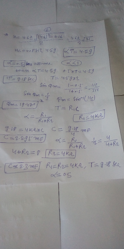
3. Consider the transfer function of a DC motor given by 1 G(s) s (s2) The objective of this question is to consider the problem of control design for this DC motor, with the feedback control architecture shown in the figure below d(t r(t) e(t) e(t) C(s) G(s) Figure 4: A feedback control system (a) Find the magnitude and the phase of the frequency response...
Consider the transfer function of a DC motor given by G(s) = 1 /
s(s+2)
3. Consider the transfer function of a DC motor given by 1 G(s) s (s2) The objective of this question is to consider the problem of control design for this DC motor, with the feedback control architecture shown in the figure below d(t r(t) e(t) e(t) C(s) G(s) Figure 4: A feedback control system (a) Find the magnitude and the phase of the frequency response...
Consider a system modelled by means of the following transfer function 10 G(s) s(s +1)(s +10)...
 Consider a system modelled by means of the following transfer function 10 G(s) s(s +1)(s +10) Given the standar negative feedback control structure, and the Bode plot of G(s): 1. Obtain (if possible) a lead compensator controller (C(s) Kc1+ts) that satisfies that the corresponding steady state error with respect to the ramp input is and that the overshoot is not greater than 15 per cent 2. Obtain (if possible) a lead compensator that satisfies that the correspond- ing steady state...
Problem 4. The open-loop transfer function of a unity feedback system is 20 G(s) S+1.5) (s +3.5) ...
 Problem 4. The open-loop transfer function of a unity feedback system is 20 G(s) S+1.5) (s +3.5) (s +15) (a) Design a lag-lead compensator for G(s) using root locus so that the closed-loop system satisfies the design specifications. (b) Design a PID compensator for G(s) using root locus so that the closed-loop system satisfies the design specifications. Design specifications -SSE to a unit step reference input is less than 0.02. Overshoot is less than 20%. Peak time is less than...
10 Q.1 Figure Q1 shows a speed control system where Gi(s) 0.5s 1' and K(s)kp K(s) G,(s) Figure Q1: Speed Control System a) Determine the transfer function from d to y (4 marks) (b) Assuming the r...
 10 Q.1 Figure Q1 shows a speed control system where Gi(s) 0.5s 1' and K(s)kp K(s) G,(s) Figure Q1: Speed Control System a) Determine the transfer function from d to y (4 marks) (b) Assuming the reference is zero, what is the steady-state error (e-r - y), in this case, you want yss since r 0) due to an unit step disturbance in d? What must the value of k be in order to make the steady-state error less than...
Lag Compensator Design Using Root-Locus 2. Consider the unity feedback system in Figure 1 for G(s...
 Lag Compensator Design Using Root-Locus 2. Consider the unity feedback system in Figure 1 for G(s)- s(s+3(s6) Design a lag compensation to meet the following specifications The step response settling time is to be less than 5 sec. . The step response overshoot is to be less than 17% . The steady-state error to a unit ramp input must not exceed 10%. Dynamic specifications (overshoot and settling time) can be met using proportional feedback, but a lag compensator is needed...
Problem 4. The open-loop transfer function of a unity feedback system is: 20 (s+1.5)(s 3.5) (s 15...
 Problem 4. The open-loop transfer function of a unity feedback system is: 20 (s+1.5)(s 3.5) (s 15) G(s) (a) Design a lag-lead compensator for G(s) using root locus so that the closed-loop system satisfies the design specifications (b) Design a PID compensator for G (s) using root locus so that the clos ed-loop system satisfies the design specifications. Design specifications .SSE to a unit step reference input is less than 0.02. Overshoot is less than 20% Peak time is less...
urgent!! II Lag/lead Compensator Design A certain plant with unity feedback has the model given by GP(s) s(1 +0.1s) (1 0.2s) Design a phase-lag OR phase-lead compensator such that: 1. The steady-...
 urgent!!
II Lag/lead Compensator Design A certain plant with unity feedback has the model given by GP(s) s(1 +0.1s) (1 0.2s) Design a phase-lag OR phase-lead compensator such that: 1. The steady- state error with respect to a unit ramp input is no more than 0.01; 2. Phase margin is approximately 40
II Lag/lead Compensator Design A certain plant with unity feedback has the model given by GP(s) s(1 +0.1s) (1 0.2s) Design a phase-lag OR phase-lead compensator such that:...
urgent!!
II Lag/lead Compensator Design A certain plant with unity feedback has the model given by GP(s) s(1 +0.1s) (1 0.2s) Design a phase-lag OR phase-lead compensator such that: 1. The steady- state error with respect to a unit ramp input is no more than 0.01; 2. Phase margin is approximately 40
II Lag/lead Compensator Design A certain plant with unity feedback has the model given by GP(s) s(1 +0.1s) (1 0.2s) Design a phase-lag OR phase-lead compensator such that:...
Probleni 4 The transfer function of the process of a unity-feedback system 1 G, (s) =...
 Probleni 4 The transfer function of the process of a unity-feedback system 1 G, (s) = 2500K s(s+25) Design a phase-lead controller with the transfer function Ge (s) 1+aTs 1+Ts So that i. The steady-state error due to a unit ramp should be less than or ii. The phase margin of the system should be greater than 45 equal to 1 percent.
SOLVE USING MATLAB A servomechanism position control has the plant transfer function 10 s(s +1) (s 10) You are to desig...
 SOLVE USING MATLAB
A servomechanism position control has the plant transfer function 10 s(s +1) (s 10) You are to design a series compensation transfer function D(s) in the unity feedback configuration to meet the following closed-loop specifications: . The response to a reference step input is to have no more than 16% overshoot. . The response to a reference step input is to have a rise time of no more than 0.4 sec. The steady-state error to a unit...
SOLVE USING MATLAB
A servomechanism position control has the plant transfer function 10 s(s +1) (s 10) You are to design a series compensation transfer function D(s) in the unity feedback configuration to meet the following closed-loop specifications: . The response to a reference step input is to have no more than 16% overshoot. . The response to a reference step input is to have a rise time of no more than 0.4 sec. The steady-state error to a unit...
Consider the electro-mechanical feedback control system shown in Figure 3. The voltage Ea(s) - Liea(t)) is...
 Consider the electro-mechanical feedback control system shown in Figure 3. The voltage Ea(s) - Liea(t)) is generated by an amplifier whose transfer function is Ga(s) -5 The position sensor has a transfer function H(s) 1 and the pre-compensator transfer function is pot X (s) Ea(s) The "Electro-Mechanical System" block, is X(s) Ea(s) 5.05s3 101s2 +505.2s 100 R(s) Amplifier, |Ea(S)Electro-MechanicalX(S) Controller, Gc(s) K, pot Ga(s) System, G(s) Encoder H(s) Figure 3: Electro-mechanical control system for Question 3 Consider a proportional controller...
 Consider the transfer function of a DC motor given by G(s) = 1 /
s(s+2)
3. Consider the transfer function of a DC motor given by 1 G(s) s (s2) The objective of this question is to consider the problem of control design for this DC motor, with the feedback control architecture shown in the figure below d(t r(t) e(t) e(t) C(s) G(s) Figure 4: A feedback control system (a) Find the magnitude and the phase of the frequency response...
Consider the transfer function of a DC motor given by G(s) = 1 /
s(s+2)
3. Consider the transfer function of a DC motor given by 1 G(s) s (s2) The objective of this question is to consider the problem of control design for this DC motor, with the feedback control architecture shown in the figure below d(t r(t) e(t) e(t) C(s) G(s) Figure 4: A feedback control system (a) Find the magnitude and the phase of the frequency response...
 Consider a system modelled by means of the following transfer function 10 G(s) s(s +1)(s +10) Given the standar negative feedback control structure, and the Bode plot of G(s): 1. Obtain (if possible) a lead compensator controller (C(s) Kc1+ts) that satisfies that the corresponding steady state error with respect to the ramp input is and that the overshoot is not greater than 15 per cent 2. Obtain (if possible) a lead compensator that satisfies that the correspond- ing steady state...
 Problem 4. The open-loop transfer function of a unity feedback system is 20 G(s) S+1.5) (s +3.5) (s +15) (a) Design a lag-lead compensator for G(s) using root locus so that the closed-loop system satisfies the design specifications. (b) Design a PID compensator for G(s) using root locus so that the closed-loop system satisfies the design specifications. Design specifications -SSE to a unit step reference input is less than 0.02. Overshoot is less than 20%. Peak time is less than...
 10 Q.1 Figure Q1 shows a speed control system where Gi(s) 0.5s 1' and K(s)kp K(s) G,(s) Figure Q1: Speed Control System a) Determine the transfer function from d to y (4 marks) (b) Assuming the reference is zero, what is the steady-state error (e-r - y), in this case, you want yss since r 0) due to an unit step disturbance in d? What must the value of k be in order to make the steady-state error less than...
 Lag Compensator Design Using Root-Locus 2. Consider the unity feedback system in Figure 1 for G(s)- s(s+3(s6) Design a lag compensation to meet the following specifications The step response settling time is to be less than 5 sec. . The step response overshoot is to be less than 17% . The steady-state error to a unit ramp input must not exceed 10%. Dynamic specifications (overshoot and settling time) can be met using proportional feedback, but a lag compensator is needed...
 Problem 4. The open-loop transfer function of a unity feedback system is: 20 (s+1.5)(s 3.5) (s 15) G(s) (a) Design a lag-lead compensator for G(s) using root locus so that the closed-loop system satisfies the design specifications (b) Design a PID compensator for G (s) using root locus so that the clos ed-loop system satisfies the design specifications. Design specifications .SSE to a unit step reference input is less than 0.02. Overshoot is less than 20% Peak time is less...
 urgent!!
II Lag/lead Compensator Design A certain plant with unity feedback has the model given by GP(s) s(1 +0.1s) (1 0.2s) Design a phase-lag OR phase-lead compensator such that: 1. The steady- state error with respect to a unit ramp input is no more than 0.01; 2. Phase margin is approximately 40
II Lag/lead Compensator Design A certain plant with unity feedback has the model given by GP(s) s(1 +0.1s) (1 0.2s) Design a phase-lag OR phase-lead compensator such that:...
urgent!!
II Lag/lead Compensator Design A certain plant with unity feedback has the model given by GP(s) s(1 +0.1s) (1 0.2s) Design a phase-lag OR phase-lead compensator such that: 1. The steady- state error with respect to a unit ramp input is no more than 0.01; 2. Phase margin is approximately 40
II Lag/lead Compensator Design A certain plant with unity feedback has the model given by GP(s) s(1 +0.1s) (1 0.2s) Design a phase-lag OR phase-lead compensator such that:...
 Probleni 4 The transfer function of the process of a unity-feedback system 1 G, (s) = 2500K s(s+25) Design a phase-lead controller with the transfer function Ge (s) 1+aTs 1+Ts So that i. The steady-state error due to a unit ramp should be less than or ii. The phase margin of the system should be greater than 45 equal to 1 percent.
 SOLVE USING MATLAB
A servomechanism position control has the plant transfer function 10 s(s +1) (s 10) You are to design a series compensation transfer function D(s) in the unity feedback configuration to meet the following closed-loop specifications: . The response to a reference step input is to have no more than 16% overshoot. . The response to a reference step input is to have a rise time of no more than 0.4 sec. The steady-state error to a unit...
SOLVE USING MATLAB
A servomechanism position control has the plant transfer function 10 s(s +1) (s 10) You are to design a series compensation transfer function D(s) in the unity feedback configuration to meet the following closed-loop specifications: . The response to a reference step input is to have no more than 16% overshoot. . The response to a reference step input is to have a rise time of no more than 0.4 sec. The steady-state error to a unit...
 Consider the electro-mechanical feedback control system shown in Figure 3. The voltage Ea(s) - Liea(t)) is generated by an amplifier whose transfer function is Ga(s) -5 The position sensor has a transfer function H(s) 1 and the pre-compensator transfer function is pot X (s) Ea(s) The "Electro-Mechanical System" block, is X(s) Ea(s) 5.05s3 101s2 +505.2s 100 R(s) Amplifier, |Ea(S)Electro-MechanicalX(S) Controller, Gc(s) K, pot Ga(s) System, G(s) Encoder H(s) Figure 3: Electro-mechanical control system for Question 3 Consider a proportional controller...
Most questions answered within 3 hours.
-
Let X be a continuous random variable whose PDF is Let X be a
continuous random...
asked 5 minutes ago -
Martinez Company’s relevant range of production is 7,500 units
to 12,500 units. When it produces and...
asked 3 minutes ago -
A football with a mass of 1.2 kg is kicked from ground level to
a height...
asked 9 minutes ago -
Remember: Changes in supply determinants shift supply, and
changes in demand determinants shift demand. We say...
asked 8 minutes ago -
Why is the answer b), for this question? I came up with C) for
my incorrect...
asked 14 minutes ago -
Suppose that you know that in the population of full-time
employees in the United States, the...
asked 36 minutes ago -
This experiment was designed originally to sample various meat and carcass quality
aspects of Ontario pigs...
asked 36 minutes ago -
Dopamine Hydrochloride: draw the structure And Show the
functional groups in different colors and label the...
asked 28 minutes ago -
A rope supports a 10 kg dumbbell hanging from it. What is the
tension in the...
asked 28 minutes ago -
) Raw materials are studied for contamination. Suppose that
the number of particles of contamination per...
asked 50 minutes ago -
After running a regression analysis we calculated an F test and
the significance level was 0.15....
asked 46 minutes ago -
----Can someone please help me solve this one using JAVA
----I thank you in advance
Create...
asked 51 minutes ago