
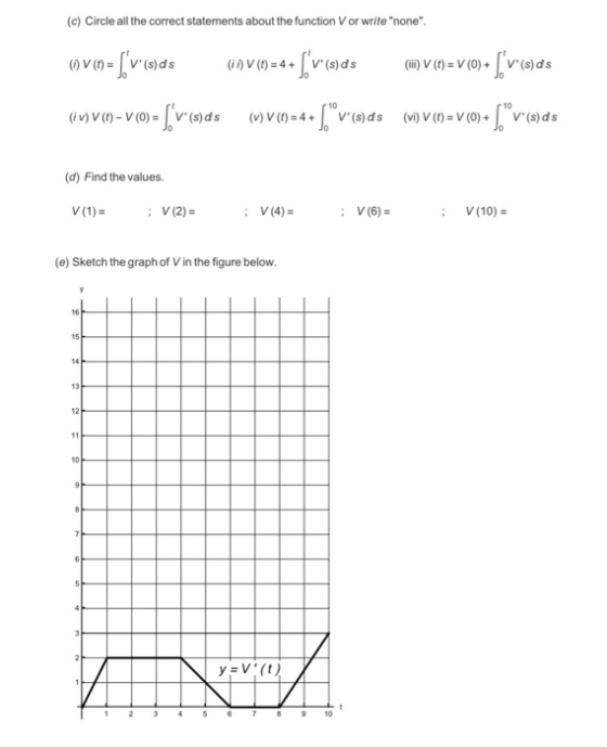

(c) Circle all the correct statements about the function V or write "none" ( V() V' (s)ds i) V (t) 4V(s)ds (ii) V (t) V(0)+V(s)ds uwvn-vo-[vods.ods (ovn-v 10 10 (i v) V(t)- V (0)V (s)ds (v) V (t)-4V(s)ds (vi) V (t)-V(0)V(s)ds (d) Find the values. V(10)- : V(4) V(6) : (e) Sketch the graph of V in the figure below. 13 12 10 6 78910
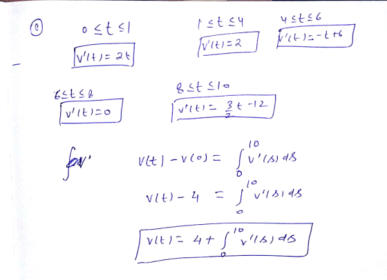
(f) Find an expression for V (t), 0sts 10. 0sts1 44ts6 V (t)- , 8
Homework Answers
Add Answer to:
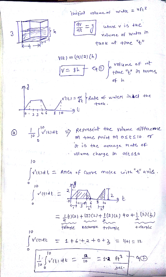
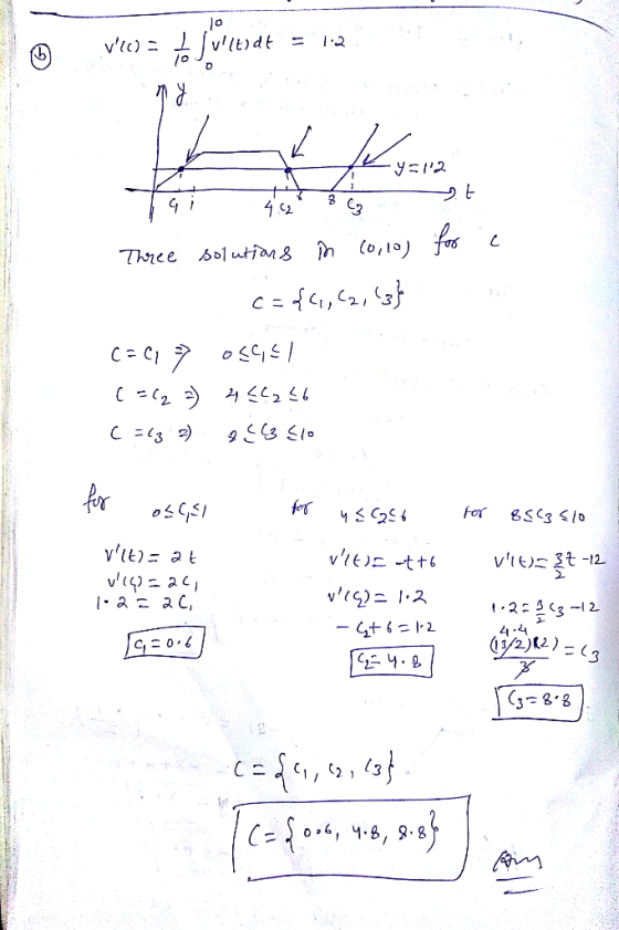
1.(4 pts) A rectangular tank, shown in Figure A, is 4 ft long, 2 ft wide, and 3 ft high. Initiall...
3) As shown in the figure below, water (o 1.94 slugs/ ft') is pumped from a large tank (1) at a r...
 3) As shown in the figure below, water (o 1.94 slugs/ ft') is pumped from a large tank (1) at a rate of 3 ft'/s through a main supply line to the top of an aeration column (2), which is a large free surface open to the atmosphere. The head loss through the supply line is 4 ft. In the acration column, the water is entrained with air as it moves downward via gravity through the column and exits to...
(3 points) Consider the two tank apparatus shown in the figure. Each tank has capacity 950950 liters and initially c...
 (3 points)
Consider the two tank apparatus shown in the figure. Each tank
has capacity 950950 liters and initially contains 100100 liters of
fresh water. At time t=0t=0, the well-stirred mixing process
begins. Suppose that the concentration of brine flowing into Tank 1
via the top tube is 11 kilograms per liter, and that the flow rates
are r1=r3=4r1=r3=4 liters per minute, and r2=r4=13r2=r4=13 liters
per minute.
(a) Determine the volume of solution in each tank as a function of...
(3 points)
Consider the two tank apparatus shown in the figure. Each tank
has capacity 950950 liters and initially contains 100100 liters of
fresh water. At time t=0t=0, the well-stirred mixing process
begins. Suppose that the concentration of brine flowing into Tank 1
via the top tube is 11 kilograms per liter, and that the flow rates
are r1=r3=4r1=r3=4 liters per minute, and r2=r4=13r2=r4=13 liters
per minute.
(a) Determine the volume of solution in each tank as a function of...
1 Tank 1 12 Tank 2 '3 (1 point Consider the two tank apparatus shown in...
 1 Tank 1 12 Tank 2 '3 (1 point Consider the two tank apparatus shown in the figure. Each tank has capacity 750 liters and initially contains 150 liters of fresh water. At time t = 0, the well-stirred mixing process begins. Suppose that the concentration of brine flowing into Tank 1 via the top tube is 1 kilograms per liter, and that the flow rates are r1 = r3 = 4 liters per minute, and r2 = r4 =...
1. Consider the following figure below that shows two brine tanks r galmin fresh water Tank 1 ank...
 1. Consider the following figure below that shows two brine tanks r galmin fresh water Tank 1 anks 2 containing and V, gallons of brine respectively. Fresh water flows into tank 1, while mixed brine flows from tank l into tank 2· Let x(1) denote the amount (in pounds) ofsalt in tank i at time for i-1,2. Ifeach flow rate is r gallons per minute, then a simple account of salt concentration yields the first-order system where 1,2 If V-50,...
(1 point) Consider the two tank apparatus shown in the figure. Each tank has capacity 750...
 (1 point) Consider the two tank apparatus shown in the figure. Each tank has capacity 750 liters and initially contains 150 liters of fresh water. At time t = 0, the well-stirred mixing process begins. Suppose that the concentration of brine flowing into Tank 1 via the top tube is 0.75 kilograms per liter, and that the flow rates are r = 13 = 3 liters per minute, and r2 = 14 = 10 liters per minute. (a) Determine the...
1. Consider the following figure below that shows two brine tanks r gal/min fresh water Tank 1 an...
 1. Consider the following figure below that shows two brine tanks r gal/min fresh water Tank 1 anks 2 containing V and V gallons of brine respectively. Fresh water flows into tank 1, while mixed brine flows from tank 1 into tank 2. Let x,() denote the amount (in pounds) of salt in tank i at time for i-1,2. If each flow rate is r gallons per minute, then a simple account of salt concentration yields the first-order system where...
A rectangular gate having a width of 4 ft is located in the sloping side of a tank as shown in the figure below. The gate is hinged along its top edge and is held in position by the force P. Friction...
 A rectangular gate having a width of 4 ft is located in the sloping side of a tank as shown in the figure below. The gate is hinged along its top edge and is held in position by the force P. Friction at the hinge and the weight of the gate can be neglected. Determine the required value of P. Water 29 ft Hinge Gate 60° lb
A rectangular gate having a width of 4 ft is located in the...
A rectangular gate having a width of 4 ft is located in the sloping side of a tank as shown in the figure below. The gate is hinged along its top edge and is held in position by the force P. Friction at the hinge and the weight of the gate can be neglected. Determine the required value of P. Water 29 ft Hinge Gate 60° lb
A rectangular gate having a width of 4 ft is located in the...
Each of the tanks shown in Figure 3.2.9 contains a brine solution. Assume that Tank 1...
 Each of the tanks shown in Figure 3.2.9 contains a brine solution. Assume that Tank 1 initially contains 30 gallons (gal) of water and 55 ounces (oz) of salt, and Tank 2 initially contains 20 gal of water and 26 oz of salt. Water containing 1 oz/gal of salt flows into Tank 1 at a rate of 1.5 gal/min, and the well-stirred solution flows from Tank 1 to Tank 2 at a rate of 3 gal/min. Additionally, water containing 3...
The open cylindrical tank in the figure contains water and is being filled as shown. Assume...
 The
open cylindrical tank in the figure contains water and is being
filled as shown. Assume incompressible flow with pwater = 1000
kg/m^3.
1. (15 marks): The open cylindrical tank in the figure contains water and is being filled as shown. Assume incompressible flow, with water = 1000 kg/m3. a) Write the mass transport equation and note that the flow may not be steady, which implies that the rate of change of mass in the control volume needs not be...
The
open cylindrical tank in the figure contains water and is being
filled as shown. Assume incompressible flow with pwater = 1000
kg/m^3.
1. (15 marks): The open cylindrical tank in the figure contains water and is being filled as shown. Assume incompressible flow, with water = 1000 kg/m3. a) Write the mass transport equation and note that the flow may not be steady, which implies that the rate of change of mass in the control volume needs not be...
The level ho of liquid in a vertical cylindrical tank as shown in Figure 4 is related to the infl...
 please answer all of part i really need them ASAP ...
The level ho of liquid in a vertical cylindrical tank as shown in Figure 4 is related to the inflow of liquid qi by the time domain equation d h dt where τ RLGL, the steady state gain of the system is G RL/pg and the tank capacitance, inlet ine ho outlet vave Tank Figure 4: Tank Level Process (a) You carry out some measurements on the tank and...
please answer all of part i really need them ASAP ...
The level ho of liquid in a vertical cylindrical tank as shown in Figure 4 is related to the inflow of liquid qi by the time domain equation d h dt where τ RLGL, the steady state gain of the system is G RL/pg and the tank capacitance, inlet ine ho outlet vave Tank Figure 4: Tank Level Process (a) You carry out some measurements on the tank and...
 3) As shown in the figure below, water (o 1.94 slugs/ ft') is pumped from a large tank (1) at a rate of 3 ft'/s through a main supply line to the top of an aeration column (2), which is a large free surface open to the atmosphere. The head loss through the supply line is 4 ft. In the acration column, the water is entrained with air as it moves downward via gravity through the column and exits to...
 (3 points)
Consider the two tank apparatus shown in the figure. Each tank
has capacity 950950 liters and initially contains 100100 liters of
fresh water. At time t=0t=0, the well-stirred mixing process
begins. Suppose that the concentration of brine flowing into Tank 1
via the top tube is 11 kilograms per liter, and that the flow rates
are r1=r3=4r1=r3=4 liters per minute, and r2=r4=13r2=r4=13 liters
per minute.
(a) Determine the volume of solution in each tank as a function of...
(3 points)
Consider the two tank apparatus shown in the figure. Each tank
has capacity 950950 liters and initially contains 100100 liters of
fresh water. At time t=0t=0, the well-stirred mixing process
begins. Suppose that the concentration of brine flowing into Tank 1
via the top tube is 11 kilograms per liter, and that the flow rates
are r1=r3=4r1=r3=4 liters per minute, and r2=r4=13r2=r4=13 liters
per minute.
(a) Determine the volume of solution in each tank as a function of...
 1 Tank 1 12 Tank 2 '3 (1 point Consider the two tank apparatus shown in the figure. Each tank has capacity 750 liters and initially contains 150 liters of fresh water. At time t = 0, the well-stirred mixing process begins. Suppose that the concentration of brine flowing into Tank 1 via the top tube is 1 kilograms per liter, and that the flow rates are r1 = r3 = 4 liters per minute, and r2 = r4 =...
 1. Consider the following figure below that shows two brine tanks r galmin fresh water Tank 1 anks 2 containing and V, gallons of brine respectively. Fresh water flows into tank 1, while mixed brine flows from tank l into tank 2· Let x(1) denote the amount (in pounds) ofsalt in tank i at time for i-1,2. Ifeach flow rate is r gallons per minute, then a simple account of salt concentration yields the first-order system where 1,2 If V-50,...
 (1 point) Consider the two tank apparatus shown in the figure. Each tank has capacity 750 liters and initially contains 150 liters of fresh water. At time t = 0, the well-stirred mixing process begins. Suppose that the concentration of brine flowing into Tank 1 via the top tube is 0.75 kilograms per liter, and that the flow rates are r = 13 = 3 liters per minute, and r2 = 14 = 10 liters per minute. (a) Determine the...
 1. Consider the following figure below that shows two brine tanks r gal/min fresh water Tank 1 anks 2 containing V and V gallons of brine respectively. Fresh water flows into tank 1, while mixed brine flows from tank 1 into tank 2. Let x,() denote the amount (in pounds) of salt in tank i at time for i-1,2. If each flow rate is r gallons per minute, then a simple account of salt concentration yields the first-order system where...
 A rectangular gate having a width of 4 ft is located in the sloping side of a tank as shown in the figure below. The gate is hinged along its top edge and is held in position by the force P. Friction at the hinge and the weight of the gate can be neglected. Determine the required value of P. Water 29 ft Hinge Gate 60° lb
A rectangular gate having a width of 4 ft is located in the...
A rectangular gate having a width of 4 ft is located in the sloping side of a tank as shown in the figure below. The gate is hinged along its top edge and is held in position by the force P. Friction at the hinge and the weight of the gate can be neglected. Determine the required value of P. Water 29 ft Hinge Gate 60° lb
A rectangular gate having a width of 4 ft is located in the...
 Each of the tanks shown in Figure 3.2.9 contains a brine solution. Assume that Tank 1 initially contains 30 gallons (gal) of water and 55 ounces (oz) of salt, and Tank 2 initially contains 20 gal of water and 26 oz of salt. Water containing 1 oz/gal of salt flows into Tank 1 at a rate of 1.5 gal/min, and the well-stirred solution flows from Tank 1 to Tank 2 at a rate of 3 gal/min. Additionally, water containing 3...
 The
open cylindrical tank in the figure contains water and is being
filled as shown. Assume incompressible flow with pwater = 1000
kg/m^3.
1. (15 marks): The open cylindrical tank in the figure contains water and is being filled as shown. Assume incompressible flow, with water = 1000 kg/m3. a) Write the mass transport equation and note that the flow may not be steady, which implies that the rate of change of mass in the control volume needs not be...
The
open cylindrical tank in the figure contains water and is being
filled as shown. Assume incompressible flow with pwater = 1000
kg/m^3.
1. (15 marks): The open cylindrical tank in the figure contains water and is being filled as shown. Assume incompressible flow, with water = 1000 kg/m3. a) Write the mass transport equation and note that the flow may not be steady, which implies that the rate of change of mass in the control volume needs not be...
 please answer all of part i really need them ASAP ...
The level ho of liquid in a vertical cylindrical tank as shown in Figure 4 is related to the inflow of liquid qi by the time domain equation d h dt where τ RLGL, the steady state gain of the system is G RL/pg and the tank capacitance, inlet ine ho outlet vave Tank Figure 4: Tank Level Process (a) You carry out some measurements on the tank and...
please answer all of part i really need them ASAP ...
The level ho of liquid in a vertical cylindrical tank as shown in Figure 4 is related to the inflow of liquid qi by the time domain equation d h dt where τ RLGL, the steady state gain of the system is G RL/pg and the tank capacitance, inlet ine ho outlet vave Tank Figure 4: Tank Level Process (a) You carry out some measurements on the tank and...
Most questions answered within 3 hours.
-
A 10.000 g sample of water contains 11.19% H by mass. what
should be the %H...
asked 2 minutes ago -
Consider an investment game among 2 players. Each player can
either invest,
i, or not invest,-i....
asked 18 seconds ago -
The time taken to complete a particular task is normally
distributed with a standard deviation of...
asked 10 minutes ago -
we have heteroskedasticity in a regression when:
When the variance of error terms changes when an...
asked 19 minutes ago -
Explain some different types of fungi. State the different
divisions undergo by fungi.
asked 32 minutes ago -
The shortest time that 120 C can flow through a 20 A circuit
breaker without tripping...
asked 33 minutes ago -
A software design pattern is a general, reusable solution to a
commonly occurring problem, acting as...
asked 35 minutes ago -
The mean waiting time at the drive-through of a fast-food
restaurant from the time an order...
asked 52 minutes ago -
The pitch (p) of a helix is defined as p = dn, in which n is...
asked 54 minutes ago -
Do you agree that the declining stock of social capital is the
blame for the failure...
asked 57 minutes ago -
A researcher is interested in whether coffee consumption helps
with performance on reading comprehension tasks. The...
asked 1 hour ago -
it has been estimated since the beginning of the human race that
about 133 metric ton...
asked 1 hour ago