In Figure 1 a conceptual diagram of a seven-segment screen is presented, called a, b, c, d, e, f and g, as well as a decimal point dp. In this work, it is not considered the decimal point.

Figure 1: Seven-Segment Screen
Each of the segments is a light-emitting diode (LED). The screen is used for representing numbers or other symbols. If the screen is a common cathode, then when a high voltage appears (logical value 1) the respective LED lights up. In Figure 2, the numerals 0 to F of the hexadecimal system are represented. Note that for the c, d and b we used lowercase letters to avoid interpretation issues. In this picture it has been assumed that a “1” is needed to turn on the LED (in black), that is, a screen has been assumed as a common cathode screen. For figures 0 and 1, it has been indicated in the respective terminals where to place 1 and where the place 0.

Figure 2: Hexadecimal Figures
In the common anode screen, the LED lights up with a logical 0, and turns off with a logical 1. In the common cathode screen, the LED lights up with a logical 1, and turns off with a logical 0. Seven-segment displays can be managed with appropriate subsystems. One of them is the codifier BCD-to-Seven-Segment, which has four entries representing a binary digit, and seven outputs to connect to the screen, so that the screen turns on the LEDs corresponding to the decimal digit corresponding to the binary of the input.
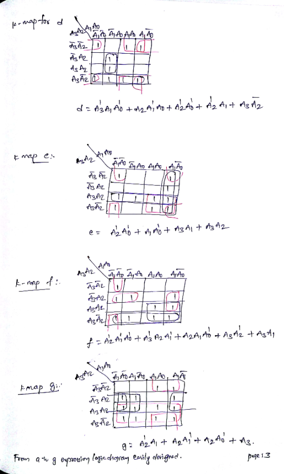
The objective of this practice is to present a design for a Gray-to-Seven- Segment as illustrated in Figure 3 according to the specifications indicated below. The Gray code is a code for numbers. In the work to be done, the A3 A2 A1 A0 entries are read as if they correspond to a number between 0 and 15 in Gray code. The screen should show the hexadecimal number placed in the entrance.

Figure 3: Encoder to Design
Question 3: If we assume a common cathode screen, place at each entry the values 1 or 0 required for the representation of each hexadecimal digit.
OD OD OD LJ
АЗ Hex A2 Gray A17 Seg to dp
Homework Answers


Add Answer to:
In Figure 1 a conceptual diagram of a seven-segment screen is presented, called a, b, c, d, e, f ...
You will build a seven-segment display decoder, shown in Figure 3. The circuit has four input...
You will build a seven-segment display decoder, shown in Figure 3. The circuit has four input bits, D3:0 (representing a hexadecimal number between 0 and F), and produces seven output bits, Sa:g, that drive the seven segments to display the number. The 7-segment display we will use in this lab is a common cathode type, a segment of the display turns on when it is 1. The other type of 7-segment display is common anode, for which a segment turns...
Program is for an Arduino 1. Add the letters “A”, “b”, “c”, “d”, “E”, “F” to...
Program is for an Arduino 1. Add the letters “A”, “b”, “c”, “d”, “E”, “F” to your homework program. Continually display “0123”, “4567”, “89Ab”, “cdEF” with a one second delay between each one. HINT: Expand pickNumber() to use numbers 10-15 (a-f in hex). Create new functions for a-f. (THIS IS THE CODE FROM THE HOMEWORK) /*************************************** name:Stopwatch function: you can see the number increases by one per second on the 4-digit 7-segment display. ***********************************/ //Email:[email protected] //Website:www.sunfounder.com /**************************************/ #include //the pins...
please answers to all thanks. Alt Car Ripple Blanking in Seven-Segment Decoders 4. In the following...
 please answers to all thanks.
Alt Car Ripple Blanking in Seven-Segment Decoders 4. In the following drawings, four 741547 seven segment decoders are configured to suppress leading or trailing zeros, using the ripple-blanking feature of the decoder a. Complete each drawing to show how to interconnect the decaders to display the digits and blank displays as shown. [2 marks for each drawing: 4 marks totall b. Label each set of decoder inputs (DCBA, RBI) and output (RBO only) with the...
please answers to all thanks.
Alt Car Ripple Blanking in Seven-Segment Decoders 4. In the following drawings, four 741547 seven segment decoders are configured to suppress leading or trailing zeros, using the ripple-blanking feature of the decoder a. Complete each drawing to show how to interconnect the decaders to display the digits and blank displays as shown. [2 marks for each drawing: 4 marks totall b. Label each set of decoder inputs (DCBA, RBI) and output (RBO only) with the...
The seven-segment indicator (shown in the figure) can be used to display any of the decimal digits 0 through 9. For example "1" is displayed by lighting segment 2 and 3 and "8" by...
 The seven-segment indicator (shown in the figure) can be used to display any of the decimal digits 0 through 9. For example "1" is displayed by lighting segment 2 and 3 and "8" by lighting all seven segments. A segment is lighted when logic 1 is applied to the corresponding input on the display module. Circuit to be aputs From Switche l p Designed Design an excess-3 code convertor to derive a seven segment indicator. The four inputs to the...
 please answers to all thanks.
Alt Car Ripple Blanking in Seven-Segment Decoders 4. In the following drawings, four 741547 seven segment decoders are configured to suppress leading or trailing zeros, using the ripple-blanking feature of the decoder a. Complete each drawing to show how to interconnect the decaders to display the digits and blank displays as shown. [2 marks for each drawing: 4 marks totall b. Label each set of decoder inputs (DCBA, RBI) and output (RBO only) with the...
please answers to all thanks.
Alt Car Ripple Blanking in Seven-Segment Decoders 4. In the following drawings, four 741547 seven segment decoders are configured to suppress leading or trailing zeros, using the ripple-blanking feature of the decoder a. Complete each drawing to show how to interconnect the decaders to display the digits and blank displays as shown. [2 marks for each drawing: 4 marks totall b. Label each set of decoder inputs (DCBA, RBI) and output (RBO only) with the...
 The seven-segment indicator (shown in the figure) can be used to display any of the decimal digits 0 through 9. For example "1" is displayed by lighting segment 2 and 3 and "8" by lighting all seven segments. A segment is lighted when logic 1 is applied to the corresponding input on the display module. Circuit to be aputs From Switche l p Designed Design an excess-3 code convertor to derive a seven segment indicator. The four inputs to the...
Most questions answered within 3 hours.
-
In reaching her destination, a backpacker walks with an average
velocity of 1.13 m/s, due west....
asked 1 minute from now -
Executive Program Practical Connection Assignment
Subject : Operations Security.
Assignment:
Provide a reflection of at least...
asked 7 minutes ago -
Every time Casey is at bat he has a 0.4 probability of
getting on base (assume...
asked 16 minutes ago -
The Walston Company is to be liquidated and has the following
liabilities:
Income taxes
$
9,400...
asked 23 minutes ago -
If
the more comprehensive data is available in MEPS, why does the NHIS
still exist? How...
asked 44 minutes ago -
Koo argues that the Japanese economy in the 1990s suffered from
a balance sheet recession. What...
asked 37 minutes ago -
Automobile mechanics conduct diagnosis tests on 150 new cars of
particular make and model to determine...
asked 31 minutes ago -
11) Find the proceeds of a 5 year non-interest
bearing note for $6500 discounted 2.5 years...
asked 38 minutes ago -
Required: Prepare the consolidated financial statements of
Griffin Ltd at 30 June 2019.
Griffin Ltd is...
asked 47 minutes ago -
1.How large must the coefficient of static friction be between
the tires and the road if...
asked 1 hour ago -
What is the time complexity (Big-O) of the following code?
class Main
{
// Recursive...
asked 1 hour ago -
Economists look at any situation in terms of its component
parts: the people making decisions, the...
asked 1 hour ago