
Homework Answers


Add Answer to:
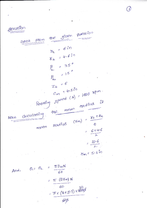
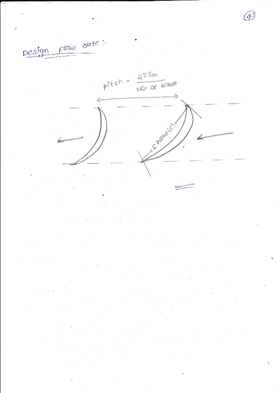
5.3 An axial-flow fan rotor with the dimensions shown is rotating at 1800rpm. Draw the velocity d...
A one stage axial air compressor consists of a rotor and a stator, it has a...
 A one stage axial air compressor consists of a rotor and a stator, it has a mean diameter of Im for the rotor and a rotational speed of 7645 RPM. Furthermore: Mass flow rate is 50 kg/s .Inlet static temperature and pressure of Ti 276 K and Pi 85 kPa. .Inlet stagnation temperature and pressure of Toi 290 K and Poi 101.3 kPa. .Inlet absolute velocity C1 166.5 m/s Rotor exit static density (p2) equals to 1.3kg/m3 Axial component of...
a twelve-bladed axial flow fan has a hydraulic efficiency of 0.92, mean radius of 0.93m and rotates at 450rpm. air enter...
a twelve-bladed axial flow fan has a hydraulic efficiency of 0.92, mean radius of 0.93m and rotates at 450rpm. air enters the blades axially at a speed of 40m/s and the head developed across the blades is 35m of air. if the cord length at the mean radius is 0.33m, find the blade angles at inlet and outlet if the blades may be considered to act as isolated aero foils. if the blades are aero foils with the following characteristics,...
TQi The rotor and stator rows arrangement of an axial compressor stage and their general velocity...
 TQi The rotor and stator rows arrangement of an axial compressor stage and their general velocity diagrams are shown in Figure 1.1 (a) and (b), respectively. The compressor rotor blade speed is set at 100 m's and the inlet absolute flow velocity for rotor (C1) and stator (C:) are given in APPENDIX A (Each student will have different data) Consider normal stage condition and constant axial flow throughout the stage at 50 m's 01 C 0 SS 93 ROTOR t=100...
Q2 Figure 2.1 shows the velocity diagram for an axial turbine stage. The turbine rotor blade...
 Q2 Figure 2.1 shows the velocity diagram for an axial turbine stage. The turbine rotor blade speed is 80 m's. Exhaust gas flow through the turbine stage with a constant axial velocity (2) at 90 m/s. List of relative and absolute flow angles at the rotor inlet and outlet are given in APPENDIX D for each student, respectively. At rotor inlet At rotor outlet B3 Cx2 = 90 m/s B2 Cx3 = 90 m/s W2 0.3 Cys 44 U =...
summatize the following info and break them into differeng key points. write them in yojr own...
 summatize the following info and break them into differeng key points. write them in yojr own words
apartus
6.1 Introduction—The design of a successful hot box appa- ratus is influenced by many factors. Before beginning the design of an apparatus meeting this standard, the designer shall review the discussion on the limitations and accuracy, Section 13, discussions of the energy flows in a hot box, Annex A2, the metering box wall loss flow, Annex A3, and flanking loss, Annex...
summatize the following info and break them into differeng key points. write them in yojr own words
apartus
6.1 Introduction—The design of a successful hot box appa- ratus is influenced by many factors. Before beginning the design of an apparatus meeting this standard, the designer shall review the discussion on the limitations and accuracy, Section 13, discussions of the energy flows in a hot box, Annex A2, the metering box wall loss flow, Annex A3, and flanking loss, Annex...
 A one stage axial air compressor consists of a rotor and a stator, it has a mean diameter of Im for the rotor and a rotational speed of 7645 RPM. Furthermore: Mass flow rate is 50 kg/s .Inlet static temperature and pressure of Ti 276 K and Pi 85 kPa. .Inlet stagnation temperature and pressure of Toi 290 K and Poi 101.3 kPa. .Inlet absolute velocity C1 166.5 m/s Rotor exit static density (p2) equals to 1.3kg/m3 Axial component of...
 TQi The rotor and stator rows arrangement of an axial compressor stage and their general velocity diagrams are shown in Figure 1.1 (a) and (b), respectively. The compressor rotor blade speed is set at 100 m's and the inlet absolute flow velocity for rotor (C1) and stator (C:) are given in APPENDIX A (Each student will have different data) Consider normal stage condition and constant axial flow throughout the stage at 50 m's 01 C 0 SS 93 ROTOR t=100...
 Q2 Figure 2.1 shows the velocity diagram for an axial turbine stage. The turbine rotor blade speed is 80 m's. Exhaust gas flow through the turbine stage with a constant axial velocity (2) at 90 m/s. List of relative and absolute flow angles at the rotor inlet and outlet are given in APPENDIX D for each student, respectively. At rotor inlet At rotor outlet B3 Cx2 = 90 m/s B2 Cx3 = 90 m/s W2 0.3 Cys 44 U =...
 summatize the following info and break them into differeng key points. write them in yojr own words
apartus
6.1 Introduction—The design of a successful hot box appa- ratus is influenced by many factors. Before beginning the design of an apparatus meeting this standard, the designer shall review the discussion on the limitations and accuracy, Section 13, discussions of the energy flows in a hot box, Annex A2, the metering box wall loss flow, Annex A3, and flanking loss, Annex...
summatize the following info and break them into differeng key points. write them in yojr own words
apartus
6.1 Introduction—The design of a successful hot box appa- ratus is influenced by many factors. Before beginning the design of an apparatus meeting this standard, the designer shall review the discussion on the limitations and accuracy, Section 13, discussions of the energy flows in a hot box, Annex A2, the metering box wall loss flow, Annex A3, and flanking loss, Annex...
Most questions answered within 3 hours.
-
While Dime Community Bank is based in Brooklyn; management has
decided to focus its lending activity...
asked 1 minute from now -
Suppose that a party wanted to enter an FRA that expires in 42
days and is...
asked 7 seconds ago -
ABC Ltd. estimated that a new store requires an initial
investment of $800,000. This new store...
asked 53 seconds ago -
1. Review the Nike’s marketing strategy. You must include the
company’s target market, possible market segmentation,...
asked 13 minutes ago -
One of the major advantages of ______________ is to enhance
security for private networks by keeping...
asked 19 minutes ago -
Book:
Title: Framework for
Marketing Management, 15th edition
Author/s: Philip T.
Kotler, Kevin Lane Keller
1....
asked 28 minutes ago -
Given Uber’s recent corporate turbulence and ongoing
initiatives, provide a holistic situational analysis of the
environment...
asked 31 minutes ago -
A sculptor has hung up a 42.0 kg horizontal rod of length 4.80 m
. One...
asked 34 minutes ago -
What is the purpose of the 2' hydroxyl group in RNA? What is
the reason this...
asked 53 minutes ago -
You currently have 20,000X ethidium bromide. You want to make
250 mL of 1X ethidium bromide...
asked 1 hour ago -
What mass of lead is needed to absorb 348 J of heat if the temp
of...
asked 1 hour ago -
Explain the difference between an auction with reserve
and an auction without reserve. if not specified,...
asked 1 hour ago