Homework Answers
(f)
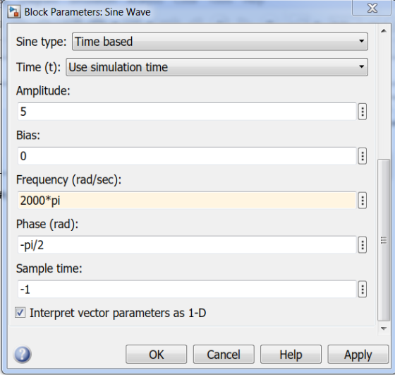
simulation result: output is available in scope.
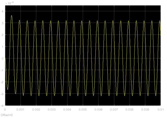
(h)
Input frequency w = 4000pi
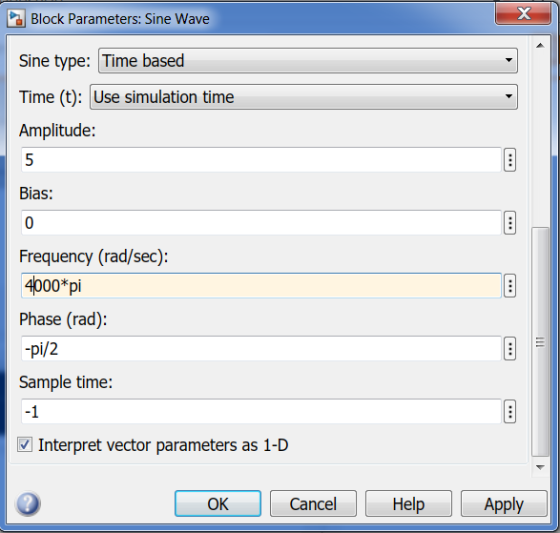
simulation result:
MATLAB code for solving the part (j) is given below in bold letters.
% (j)
clc;
close all;
clear all;
% define the frequency variable s as symbolic
variable
syms s;
% define the parameters of the transfer function
w0 = 2000*pi;Q = 5;
% Define the transfer function
H = s*(w0/Q)/(s^2+s*(w0/Q)+w0^2);
% obtain the inverse laplace transfer function of H(s),
impulse response h(t)
h = ilaplace(H);
% define time vector
t = 0:1e-5:0.01;
h_t = subs(h);
% plot the system impulse response
figure;
plot(t,h_t,'linewidth',2);grid on;xlabel('time');
ylabel('Amplitude');title('h(t)');
RESULT:

Add Answer to:
Please complete only F, H, and J only. step by step clearly. please follow the questions. also ty...
100 Consider the following LTI system, 5, and wo = 2000π rad/sec. where, Q a) Use MATLAB to deter...
 please complete this project.
100 Consider the following LTI system, 5, and wo = 2000π rad/sec. where, Q a) Use MATLAB to determine magnitude response and phase response of the filter b) What type of filter is it? c) What will be the output of this filter if input x,(t)-5Cos(100t). Show all calculations step by step as shown in Lecture-20 d) Verify your answer of part (e) by using Simulink model. Attach the snapshot of Simulink model and output e)...
please complete this project.
100 Consider the following LTI system, 5, and wo = 2000π rad/sec. where, Q a) Use MATLAB to determine magnitude response and phase response of the filter b) What type of filter is it? c) What will be the output of this filter if input x,(t)-5Cos(100t). Show all calculations step by step as shown in Lecture-20 d) Verify your answer of part (e) by using Simulink model. Attach the snapshot of Simulink model and output e)...
Clear steps, please. Consider the following LTI system where, Q -5, and w 2000m rad./sec. a)...
 Clear steps, please.
Consider the following LTI system where, Q -5, and w 2000m rad./sec. a) Use MATLAB to determine magnitude response and phase response of the filter. b) What type of filter is it? c) What will be the output of this filter if input xio- 5Cos(1000). Show all calculations step by step as shown in Lecture-21 . d) Verify your answer of part (e) by using Simulink model. Attach the snapshot of Simulink model and output. e) What...
Clear steps, please.
Consider the following LTI system where, Q -5, and w 2000m rad./sec. a) Use MATLAB to determine magnitude response and phase response of the filter. b) What type of filter is it? c) What will be the output of this filter if input xio- 5Cos(1000). Show all calculations step by step as shown in Lecture-21 . d) Verify your answer of part (e) by using Simulink model. Attach the snapshot of Simulink model and output. e) What...
All i want is the whole MATLAB code for this nothing else
 All i want is the whole MATLAB code for this nothing
else
H(s) where, Q-5, and 40-2000, rad./sec. a) Use MATLAB to determine magnitude response and phase response of the filter. b) What type of filter is it? c) What will be the output of this filter if input x,() SCos(1001). Show all calculations step by step as shown in Lecture-20 d) Verify your answer of part (c) by using Simulink model. Attach the snapshot of Simulink model and output....
All i want is the whole MATLAB code for this nothing
else
H(s) where, Q-5, and 40-2000, rad./sec. a) Use MATLAB to determine magnitude response and phase response of the filter. b) What type of filter is it? c) What will be the output of this filter if input x,() SCos(1001). Show all calculations step by step as shown in Lecture-20 d) Verify your answer of part (c) by using Simulink model. Attach the snapshot of Simulink model and output....
Consider the following LTI system where, Q-5, and wo2000T rad./sec. e) What will be the output...
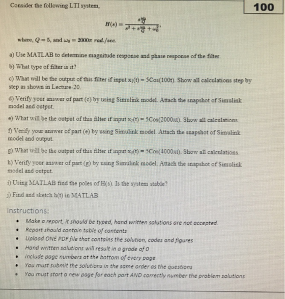
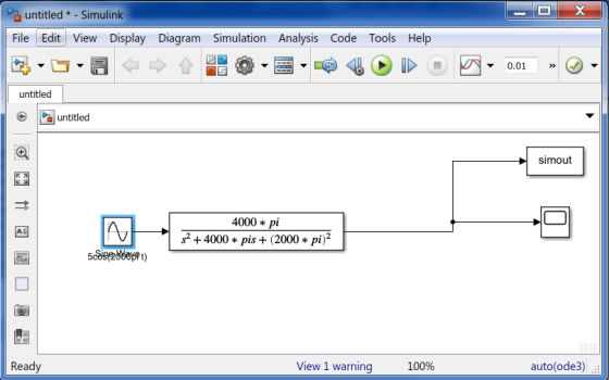
 Consider the following LTI system where, Q-5, and wo2000T rad./sec. e) What will be the output of this filter if input x2(t) = 5Cos(2000mt) Show all calculations on paper f)Verify your answer of part (e) by using Simulink model. Attach the snapshot of Simulink model and output. g What will be the output of this filter if input x(0) 5Cos(4000t). Show all calculations on paper. h) Verify your answer of part (g) by using Simulink model. Attach the snapshot of...
Please Show All the Steps Carefully. Please include both Written and Matlab approach. Written meaning Approaching...
 Please Show All the Steps Carefully. Please include both Written
and Matlab approach. Written meaning Approaching the problem by
hand and not using Matlab at all. Highest rating will be given to
those who show all the Written and Mattab steps carefully. Do not
skip the Written Method at all! Show All Your Work, Please!
2. An FIR system is described by the following Difference equation y n)-0.5 (x(n) - x(n-2)) a. Find the frequency response of this filter and...
Please Show All the Steps Carefully. Please include both Written
and Matlab approach. Written meaning Approaching the problem by
hand and not using Matlab at all. Highest rating will be given to
those who show all the Written and Mattab steps carefully. Do not
skip the Written Method at all! Show All Your Work, Please!
2. An FIR system is described by the following Difference equation y n)-0.5 (x(n) - x(n-2)) a. Find the frequency response of this filter and...
part II is what I need help one. part 1 is also attached for your reference...
 part II is what I need help one. part 1 is also
attached for your reference
Part II: Low Pass Filter contd. Noise Removal To observe the noise removal capabilities of a low -pass filter, we will add a second input to the system to simulate noise Step 1: Alter your Simulink model by adding another sine wave function and use a Sum block to add the inputs together as the new input to the system. The second sine function...
part II is what I need help one. part 1 is also
attached for your reference
Part II: Low Pass Filter contd. Noise Removal To observe the noise removal capabilities of a low -pass filter, we will add a second input to the system to simulate noise Step 1: Alter your Simulink model by adding another sine wave function and use a Sum block to add the inputs together as the new input to the system. The second sine function...
Solve the question in Matlab and please show Matlab code Consider a double Spring-Mass-Damper System as...
 Solve the question in Matlab and please show Matlab code
Consider a double Spring-Mass-Damper System as shown in the figure below: U >F(t) A. Create a Simulink model to simulate the dynamics of the above system for the following parameter values: F(t) = Step input force of magnitude 5 N ml = 7 kg, b1 = 3 Nsec/m, kl = 4 N/m m2 = 3 kg, b2 = 1 Nsec/m, k2= 2 N/m B. Submit a snapshot of the Simulink...
Solve the question in Matlab and please show Matlab code
Consider a double Spring-Mass-Damper System as shown in the figure below: U >F(t) A. Create a Simulink model to simulate the dynamics of the above system for the following parameter values: F(t) = Step input force of magnitude 5 N ml = 7 kg, b1 = 3 Nsec/m, kl = 4 N/m m2 = 3 kg, b2 = 1 Nsec/m, k2= 2 N/m B. Submit a snapshot of the Simulink...
Home-Work 5 All questions carry equal points. Don't forget to highlight your final answers 25 ues...
 Home-Work 5 All questions carry equal points. Don't forget to highlight your final answers 25 uestion # 1 Use table to find Fourier transform. Sketch the magnitude response and phase response (i) x(t) Cos(1000t) (ii) x(t) 13Cos(100t)- 7Sin(500t) (iv) x(t) rect To (v) xo)-rect ()Cos(10001) (v) x(o) -ret)Cos(000t) Question # 2 Let h(t) be a linear time invariant system, with the following transfer function s + 1 000m (a) Find H(w) (b) Sketch the magnitude and phase response of H(w)...
control system System Description: The figure 1 and 2 below show, respectively, components and block diagram...
 control system
System Description: The figure 1 and 2 below show, respectively, components and block diagram of a motor and the measurements of velocity (via the tacho unit) and position (via the potentiometer). n represents the gearbox ratio between the rotating shaft and the output shaft. The left-hand side of the diagram represents the controller. A reference set point for the rotating shaft is entered in degrees and this is equivalent voltage. The error is calculated by subtracting the measured...
control system
System Description: The figure 1 and 2 below show, respectively, components and block diagram of a motor and the measurements of velocity (via the tacho unit) and position (via the potentiometer). n represents the gearbox ratio between the rotating shaft and the output shaft. The left-hand side of the diagram represents the controller. A reference set point for the rotating shaft is entered in degrees and this is equivalent voltage. The error is calculated by subtracting the measured...
This is for Controls Systems class. Please solve everything, and show all work and correct answers...
 This is for Controls Systems class. Please solve everything, and
show all work and correct answers and matlab codes for positive
rating. A - C, E - F do by hand. D, G-I do in Matlab as
instructions direct. (Show codes and plots for
matlab solutions too!), show the code and plots obtained
for positive rating. Provided below is the Handout 7 equations that
are needed for this problem for use.
1. The state space model of a system is...
This is for Controls Systems class. Please solve everything, and
show all work and correct answers and matlab codes for positive
rating. A - C, E - F do by hand. D, G-I do in Matlab as
instructions direct. (Show codes and plots for
matlab solutions too!), show the code and plots obtained
for positive rating. Provided below is the Handout 7 equations that
are needed for this problem for use.
1. The state space model of a system is...
 please complete this project.
100 Consider the following LTI system, 5, and wo = 2000π rad/sec. where, Q a) Use MATLAB to determine magnitude response and phase response of the filter b) What type of filter is it? c) What will be the output of this filter if input x,(t)-5Cos(100t). Show all calculations step by step as shown in Lecture-20 d) Verify your answer of part (e) by using Simulink model. Attach the snapshot of Simulink model and output e)...
please complete this project.
100 Consider the following LTI system, 5, and wo = 2000π rad/sec. where, Q a) Use MATLAB to determine magnitude response and phase response of the filter b) What type of filter is it? c) What will be the output of this filter if input x,(t)-5Cos(100t). Show all calculations step by step as shown in Lecture-20 d) Verify your answer of part (e) by using Simulink model. Attach the snapshot of Simulink model and output e)...
 Clear steps, please.
Consider the following LTI system where, Q -5, and w 2000m rad./sec. a) Use MATLAB to determine magnitude response and phase response of the filter. b) What type of filter is it? c) What will be the output of this filter if input xio- 5Cos(1000). Show all calculations step by step as shown in Lecture-21 . d) Verify your answer of part (e) by using Simulink model. Attach the snapshot of Simulink model and output. e) What...
Clear steps, please.
Consider the following LTI system where, Q -5, and w 2000m rad./sec. a) Use MATLAB to determine magnitude response and phase response of the filter. b) What type of filter is it? c) What will be the output of this filter if input xio- 5Cos(1000). Show all calculations step by step as shown in Lecture-21 . d) Verify your answer of part (e) by using Simulink model. Attach the snapshot of Simulink model and output. e) What...
 All i want is the whole MATLAB code for this nothing
else
H(s) where, Q-5, and 40-2000, rad./sec. a) Use MATLAB to determine magnitude response and phase response of the filter. b) What type of filter is it? c) What will be the output of this filter if input x,() SCos(1001). Show all calculations step by step as shown in Lecture-20 d) Verify your answer of part (c) by using Simulink model. Attach the snapshot of Simulink model and output....
All i want is the whole MATLAB code for this nothing
else
H(s) where, Q-5, and 40-2000, rad./sec. a) Use MATLAB to determine magnitude response and phase response of the filter. b) What type of filter is it? c) What will be the output of this filter if input x,() SCos(1001). Show all calculations step by step as shown in Lecture-20 d) Verify your answer of part (c) by using Simulink model. Attach the snapshot of Simulink model and output....
 Consider the following LTI system where, Q-5, and wo2000T rad./sec. e) What will be the output of this filter if input x2(t) = 5Cos(2000mt) Show all calculations on paper f)Verify your answer of part (e) by using Simulink model. Attach the snapshot of Simulink model and output. g What will be the output of this filter if input x(0) 5Cos(4000t). Show all calculations on paper. h) Verify your answer of part (g) by using Simulink model. Attach the snapshot of...
 Please Show All the Steps Carefully. Please include both Written
and Matlab approach. Written meaning Approaching the problem by
hand and not using Matlab at all. Highest rating will be given to
those who show all the Written and Mattab steps carefully. Do not
skip the Written Method at all! Show All Your Work, Please!
2. An FIR system is described by the following Difference equation y n)-0.5 (x(n) - x(n-2)) a. Find the frequency response of this filter and...
Please Show All the Steps Carefully. Please include both Written
and Matlab approach. Written meaning Approaching the problem by
hand and not using Matlab at all. Highest rating will be given to
those who show all the Written and Mattab steps carefully. Do not
skip the Written Method at all! Show All Your Work, Please!
2. An FIR system is described by the following Difference equation y n)-0.5 (x(n) - x(n-2)) a. Find the frequency response of this filter and...
 part II is what I need help one. part 1 is also
attached for your reference
Part II: Low Pass Filter contd. Noise Removal To observe the noise removal capabilities of a low -pass filter, we will add a second input to the system to simulate noise Step 1: Alter your Simulink model by adding another sine wave function and use a Sum block to add the inputs together as the new input to the system. The second sine function...
part II is what I need help one. part 1 is also
attached for your reference
Part II: Low Pass Filter contd. Noise Removal To observe the noise removal capabilities of a low -pass filter, we will add a second input to the system to simulate noise Step 1: Alter your Simulink model by adding another sine wave function and use a Sum block to add the inputs together as the new input to the system. The second sine function...
 Solve the question in Matlab and please show Matlab code
Consider a double Spring-Mass-Damper System as shown in the figure below: U >F(t) A. Create a Simulink model to simulate the dynamics of the above system for the following parameter values: F(t) = Step input force of magnitude 5 N ml = 7 kg, b1 = 3 Nsec/m, kl = 4 N/m m2 = 3 kg, b2 = 1 Nsec/m, k2= 2 N/m B. Submit a snapshot of the Simulink...
Solve the question in Matlab and please show Matlab code
Consider a double Spring-Mass-Damper System as shown in the figure below: U >F(t) A. Create a Simulink model to simulate the dynamics of the above system for the following parameter values: F(t) = Step input force of magnitude 5 N ml = 7 kg, b1 = 3 Nsec/m, kl = 4 N/m m2 = 3 kg, b2 = 1 Nsec/m, k2= 2 N/m B. Submit a snapshot of the Simulink...
 Home-Work 5 All questions carry equal points. Don't forget to highlight your final answers 25 uestion # 1 Use table to find Fourier transform. Sketch the magnitude response and phase response (i) x(t) Cos(1000t) (ii) x(t) 13Cos(100t)- 7Sin(500t) (iv) x(t) rect To (v) xo)-rect ()Cos(10001) (v) x(o) -ret)Cos(000t) Question # 2 Let h(t) be a linear time invariant system, with the following transfer function s + 1 000m (a) Find H(w) (b) Sketch the magnitude and phase response of H(w)...
 control system
System Description: The figure 1 and 2 below show, respectively, components and block diagram of a motor and the measurements of velocity (via the tacho unit) and position (via the potentiometer). n represents the gearbox ratio between the rotating shaft and the output shaft. The left-hand side of the diagram represents the controller. A reference set point for the rotating shaft is entered in degrees and this is equivalent voltage. The error is calculated by subtracting the measured...
control system
System Description: The figure 1 and 2 below show, respectively, components and block diagram of a motor and the measurements of velocity (via the tacho unit) and position (via the potentiometer). n represents the gearbox ratio between the rotating shaft and the output shaft. The left-hand side of the diagram represents the controller. A reference set point for the rotating shaft is entered in degrees and this is equivalent voltage. The error is calculated by subtracting the measured...
 This is for Controls Systems class. Please solve everything, and
show all work and correct answers and matlab codes for positive
rating. A - C, E - F do by hand. D, G-I do in Matlab as
instructions direct. (Show codes and plots for
matlab solutions too!), show the code and plots obtained
for positive rating. Provided below is the Handout 7 equations that
are needed for this problem for use.
1. The state space model of a system is...
This is for Controls Systems class. Please solve everything, and
show all work and correct answers and matlab codes for positive
rating. A - C, E - F do by hand. D, G-I do in Matlab as
instructions direct. (Show codes and plots for
matlab solutions too!), show the code and plots obtained
for positive rating. Provided below is the Handout 7 equations that
are needed for this problem for use.
1. The state space model of a system is...
Most questions answered within 3 hours.
-
The average length of time between arrivals at a turnpike
toll-booth is 26 seconds. What is...
asked 1 hour ago -
(a) A piston at 6.1 atm contains a gas that occupies a volume of
3.5 L....
asked 2 hours ago -
Please answer true or false. Words
cannot be changed or added in to make it true...
asked 2 hours ago -
An empty test tube weighs 15.923 grams. Then,
MgCl2•6H2O is added into the test tube. After...
asked 2 hours ago -
Assume memory access is 10 units of time and disk access is
10000 units of time....
asked 3 hours ago -
1. Are all good samples random?
2. Magazines often report surveys giving statistics such as “63%...
asked 3 hours ago -
Under all the various types of market structures, firms
must eventually earn some economic profits for...
asked 3 hours ago -
Consider the following fitness regime for a single locus trait
with two co-dominant alleles: w11 =...
asked 3 hours ago -
A large cable company reports the following.
80% of its customers subscribe to its cable TV...
asked 3 hours ago -
Please answer the question in brief.
Discuss the role of ERP in organizations. Are ERP tools...
asked 3 hours ago -
Discuss the pros and cons of collaborative software such
as SameTime. Does it increase productivity? What...
asked 3 hours ago -
Buying your in-laws a gift because it’s expected is
due to the ____________ motive of gift-giving....
asked 3 hours ago