
Homework Answers
a) matlab code:
clc;
clear all;
s=tf('s');
q=5;
w0=2000*pi;
p=w0/q;
g=p*s/(s^2+p*s+w0^2);
margin(g); % magnitude and phase response using bode
 b) This is a band
pass filter
b) This is a band
pass filter
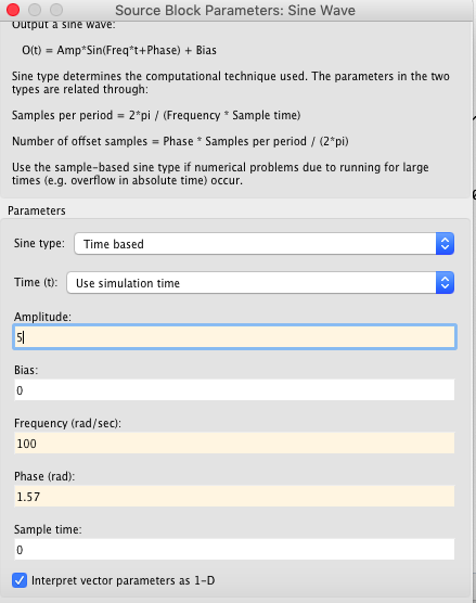
c) d)
d)
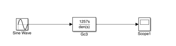
simulink:

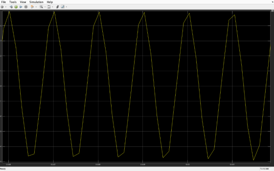
 output:
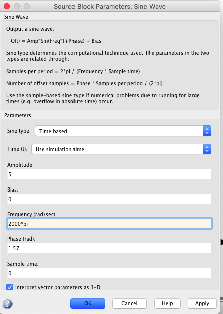
 f)
f)
Add Answer to:
100 Consider the following LTI system, 5, and wo = 2000π rad/sec. where, Q a) Use MATLAB to deter...
Clear steps, please. Consider the following LTI system where, Q -5, and w 2000m rad./sec. a)...
 Clear steps, please.
Consider the following LTI system where, Q -5, and w 2000m rad./sec. a) Use MATLAB to determine magnitude response and phase response of the filter. b) What type of filter is it? c) What will be the output of this filter if input xio- 5Cos(1000). Show all calculations step by step as shown in Lecture-21 . d) Verify your answer of part (e) by using Simulink model. Attach the snapshot of Simulink model and output. e) What...
Clear steps, please.
Consider the following LTI system where, Q -5, and w 2000m rad./sec. a) Use MATLAB to determine magnitude response and phase response of the filter. b) What type of filter is it? c) What will be the output of this filter if input xio- 5Cos(1000). Show all calculations step by step as shown in Lecture-21 . d) Verify your answer of part (e) by using Simulink model. Attach the snapshot of Simulink model and output. e) What...
Consider the following LTI system where, Q-5, and wo2000T rad./sec. e) What will be the output...
 Consider the following LTI system where, Q-5, and wo2000T rad./sec. e) What will be the output of this filter if input x2(t) = 5Cos(2000mt) Show all calculations on paper f)Verify your answer of part (e) by using Simulink model. Attach the snapshot of Simulink model and output. g What will be the output of this filter if input x(0) 5Cos(4000t). Show all calculations on paper. h) Verify your answer of part (g) by using Simulink model. Attach the snapshot of...
Please complete only F, H, and J only. step by step clearly. please follow the questions. also ty...
 please complete only F, H, and J only. step by step clearly.
please follow the questions. also type any codes you used.
100 Consider the following LTI system, where, Q = 5, and wo 200π rad. /sec. a) Use MATLAB to determine magnitude response and phase response of the filter b) What type of filter is it? c) What will be the output of this filter if input x,(t)-5Cos(100t). Show all calculations step by step as shown in Lecture-20 d)...
please complete only F, H, and J only. step by step clearly.
please follow the questions. also type any codes you used.
100 Consider the following LTI system, where, Q = 5, and wo 200π rad. /sec. a) Use MATLAB to determine magnitude response and phase response of the filter b) What type of filter is it? c) What will be the output of this filter if input x,(t)-5Cos(100t). Show all calculations step by step as shown in Lecture-20 d)...
All i want is the whole MATLAB code for this nothing else
 All i want is the whole MATLAB code for this nothing
else
H(s) where, Q-5, and 40-2000, rad./sec. a) Use MATLAB to determine magnitude response and phase response of the filter. b) What type of filter is it? c) What will be the output of this filter if input x,() SCos(1001). Show all calculations step by step as shown in Lecture-20 d) Verify your answer of part (c) by using Simulink model. Attach the snapshot of Simulink model and output....
All i want is the whole MATLAB code for this nothing
else
H(s) where, Q-5, and 40-2000, rad./sec. a) Use MATLAB to determine magnitude response and phase response of the filter. b) What type of filter is it? c) What will be the output of this filter if input x,() SCos(1001). Show all calculations step by step as shown in Lecture-20 d) Verify your answer of part (c) by using Simulink model. Attach the snapshot of Simulink model and output....
Show Matlab plot comparasion properly please 2) Let a system with an LTI model be 100...
 Show Matlab plot comparasion properly please
2) Let a system with an LTI model be 100 G(s) = 2s2 + 24s + 200 a) Determine the zeros, poles, the steady state step response (aka DC gain), the damping ratio, and the natural frequency b) Find the step response of the system manually and plot the y(t) signal on Matlab c) Use Simulink to simulate the same step response and compare both by taking the L2 norm of the error between...
Show Matlab plot comparasion properly please
2) Let a system with an LTI model be 100 G(s) = 2s2 + 24s + 200 a) Determine the zeros, poles, the steady state step response (aka DC gain), the damping ratio, and the natural frequency b) Find the step response of the system manually and plot the y(t) signal on Matlab c) Use Simulink to simulate the same step response and compare both by taking the L2 norm of the error between...
Solve the question in Matlab and please show Matlab code Consider a double Spring-Mass-Damper System as...
 Solve the question in Matlab and please show Matlab code
Consider a double Spring-Mass-Damper System as shown in the figure below: U >F(t) A. Create a Simulink model to simulate the dynamics of the above system for the following parameter values: F(t) = Step input force of magnitude 5 N ml = 7 kg, b1 = 3 Nsec/m, kl = 4 N/m m2 = 3 kg, b2 = 1 Nsec/m, k2= 2 N/m B. Submit a snapshot of the Simulink...
Solve the question in Matlab and please show Matlab code
Consider a double Spring-Mass-Damper System as shown in the figure below: U >F(t) A. Create a Simulink model to simulate the dynamics of the above system for the following parameter values: F(t) = Step input force of magnitude 5 N ml = 7 kg, b1 = 3 Nsec/m, kl = 4 N/m m2 = 3 kg, b2 = 1 Nsec/m, k2= 2 N/m B. Submit a snapshot of the Simulink...
Please Show All the Steps Carefully. Please include both Written and Matlab approach. Written meaning Approaching...
 Please Show All the Steps Carefully. Please include both Written
and Matlab approach. Written meaning Approaching the problem by
hand and not using Matlab at all. Highest rating will be given to
those who show all the Written and Mattab steps carefully. Do not
skip the Written Method at all! Show All Your Work, Please!
2. An FIR system is described by the following Difference equation y n)-0.5 (x(n) - x(n-2)) a. Find the frequency response of this filter and...
Please Show All the Steps Carefully. Please include both Written
and Matlab approach. Written meaning Approaching the problem by
hand and not using Matlab at all. Highest rating will be given to
those who show all the Written and Mattab steps carefully. Do not
skip the Written Method at all! Show All Your Work, Please!
2. An FIR system is described by the following Difference equation y n)-0.5 (x(n) - x(n-2)) a. Find the frequency response of this filter and...
a can be skipped Consider the following second-order ODE representing a spring-mass-damper system for zero initial...
 a can be skipped
Consider the following second-order ODE representing a spring-mass-damper system for zero initial conditions (forced response): 2x + 2x + x=u, x(0) = 0, *(0) = 0 where u is the Unit Step Function (of magnitude 1). a. Use MATLAB to obtain an analytical solution x(t) for the differential equation, using the Laplace Transforms approach (do not use DSOLVE). Obtain the analytical expression for x(t). Also obtain a plot of .x(t) (for a simulation of 14 seconds)...
a can be skipped
Consider the following second-order ODE representing a spring-mass-damper system for zero initial conditions (forced response): 2x + 2x + x=u, x(0) = 0, *(0) = 0 where u is the Unit Step Function (of magnitude 1). a. Use MATLAB to obtain an analytical solution x(t) for the differential equation, using the Laplace Transforms approach (do not use DSOLVE). Obtain the analytical expression for x(t). Also obtain a plot of .x(t) (for a simulation of 14 seconds)...
Consider the following second-order ODE representing a spring-mass-damper system for zero initial...
 Consider the following second-order ODE representing a spring-mass-damper system for zero initial conditions (forced response): where u is the Unit Step Function (of magnitude 1 a. Use MATLAB to obtain an analytical solution x() for the differential equation, using the Laplace Transforms approach (do not use DSOLVE). Obtain the analytical expression for ao. Also obtain a plot of x() (for a simulation of 14 seconds) b. Obtain the Transfer Function representation for the system. c. Use MATLAB to obtain the...
control system System Description: The figure 1 and 2 below show, respectively, components and block diagram...
 control system
System Description: The figure 1 and 2 below show, respectively, components and block diagram of a motor and the measurements of velocity (via the tacho unit) and position (via the potentiometer). n represents the gearbox ratio between the rotating shaft and the output shaft. The left-hand side of the diagram represents the controller. A reference set point for the rotating shaft is entered in degrees and this is equivalent voltage. The error is calculated by subtracting the measured...
control system
System Description: The figure 1 and 2 below show, respectively, components and block diagram of a motor and the measurements of velocity (via the tacho unit) and position (via the potentiometer). n represents the gearbox ratio between the rotating shaft and the output shaft. The left-hand side of the diagram represents the controller. A reference set point for the rotating shaft is entered in degrees and this is equivalent voltage. The error is calculated by subtracting the measured...
 Clear steps, please.
Consider the following LTI system where, Q -5, and w 2000m rad./sec. a) Use MATLAB to determine magnitude response and phase response of the filter. b) What type of filter is it? c) What will be the output of this filter if input xio- 5Cos(1000). Show all calculations step by step as shown in Lecture-21 . d) Verify your answer of part (e) by using Simulink model. Attach the snapshot of Simulink model and output. e) What...
Clear steps, please.
Consider the following LTI system where, Q -5, and w 2000m rad./sec. a) Use MATLAB to determine magnitude response and phase response of the filter. b) What type of filter is it? c) What will be the output of this filter if input xio- 5Cos(1000). Show all calculations step by step as shown in Lecture-21 . d) Verify your answer of part (e) by using Simulink model. Attach the snapshot of Simulink model and output. e) What...
 Consider the following LTI system where, Q-5, and wo2000T rad./sec. e) What will be the output of this filter if input x2(t) = 5Cos(2000mt) Show all calculations on paper f)Verify your answer of part (e) by using Simulink model. Attach the snapshot of Simulink model and output. g What will be the output of this filter if input x(0) 5Cos(4000t). Show all calculations on paper. h) Verify your answer of part (g) by using Simulink model. Attach the snapshot of...
 please complete only F, H, and J only. step by step clearly.
please follow the questions. also type any codes you used.
100 Consider the following LTI system, where, Q = 5, and wo 200π rad. /sec. a) Use MATLAB to determine magnitude response and phase response of the filter b) What type of filter is it? c) What will be the output of this filter if input x,(t)-5Cos(100t). Show all calculations step by step as shown in Lecture-20 d)...
please complete only F, H, and J only. step by step clearly.
please follow the questions. also type any codes you used.
100 Consider the following LTI system, where, Q = 5, and wo 200π rad. /sec. a) Use MATLAB to determine magnitude response and phase response of the filter b) What type of filter is it? c) What will be the output of this filter if input x,(t)-5Cos(100t). Show all calculations step by step as shown in Lecture-20 d)...
 All i want is the whole MATLAB code for this nothing
else
H(s) where, Q-5, and 40-2000, rad./sec. a) Use MATLAB to determine magnitude response and phase response of the filter. b) What type of filter is it? c) What will be the output of this filter if input x,() SCos(1001). Show all calculations step by step as shown in Lecture-20 d) Verify your answer of part (c) by using Simulink model. Attach the snapshot of Simulink model and output....
All i want is the whole MATLAB code for this nothing
else
H(s) where, Q-5, and 40-2000, rad./sec. a) Use MATLAB to determine magnitude response and phase response of the filter. b) What type of filter is it? c) What will be the output of this filter if input x,() SCos(1001). Show all calculations step by step as shown in Lecture-20 d) Verify your answer of part (c) by using Simulink model. Attach the snapshot of Simulink model and output....
 Show Matlab plot comparasion properly please
2) Let a system with an LTI model be 100 G(s) = 2s2 + 24s + 200 a) Determine the zeros, poles, the steady state step response (aka DC gain), the damping ratio, and the natural frequency b) Find the step response of the system manually and plot the y(t) signal on Matlab c) Use Simulink to simulate the same step response and compare both by taking the L2 norm of the error between...
Show Matlab plot comparasion properly please
2) Let a system with an LTI model be 100 G(s) = 2s2 + 24s + 200 a) Determine the zeros, poles, the steady state step response (aka DC gain), the damping ratio, and the natural frequency b) Find the step response of the system manually and plot the y(t) signal on Matlab c) Use Simulink to simulate the same step response and compare both by taking the L2 norm of the error between...
 Solve the question in Matlab and please show Matlab code
Consider a double Spring-Mass-Damper System as shown in the figure below: U >F(t) A. Create a Simulink model to simulate the dynamics of the above system for the following parameter values: F(t) = Step input force of magnitude 5 N ml = 7 kg, b1 = 3 Nsec/m, kl = 4 N/m m2 = 3 kg, b2 = 1 Nsec/m, k2= 2 N/m B. Submit a snapshot of the Simulink...
Solve the question in Matlab and please show Matlab code
Consider a double Spring-Mass-Damper System as shown in the figure below: U >F(t) A. Create a Simulink model to simulate the dynamics of the above system for the following parameter values: F(t) = Step input force of magnitude 5 N ml = 7 kg, b1 = 3 Nsec/m, kl = 4 N/m m2 = 3 kg, b2 = 1 Nsec/m, k2= 2 N/m B. Submit a snapshot of the Simulink...
 Please Show All the Steps Carefully. Please include both Written
and Matlab approach. Written meaning Approaching the problem by
hand and not using Matlab at all. Highest rating will be given to
those who show all the Written and Mattab steps carefully. Do not
skip the Written Method at all! Show All Your Work, Please!
2. An FIR system is described by the following Difference equation y n)-0.5 (x(n) - x(n-2)) a. Find the frequency response of this filter and...
Please Show All the Steps Carefully. Please include both Written
and Matlab approach. Written meaning Approaching the problem by
hand and not using Matlab at all. Highest rating will be given to
those who show all the Written and Mattab steps carefully. Do not
skip the Written Method at all! Show All Your Work, Please!
2. An FIR system is described by the following Difference equation y n)-0.5 (x(n) - x(n-2)) a. Find the frequency response of this filter and...
 a can be skipped
Consider the following second-order ODE representing a spring-mass-damper system for zero initial conditions (forced response): 2x + 2x + x=u, x(0) = 0, *(0) = 0 where u is the Unit Step Function (of magnitude 1). a. Use MATLAB to obtain an analytical solution x(t) for the differential equation, using the Laplace Transforms approach (do not use DSOLVE). Obtain the analytical expression for x(t). Also obtain a plot of .x(t) (for a simulation of 14 seconds)...
a can be skipped
Consider the following second-order ODE representing a spring-mass-damper system for zero initial conditions (forced response): 2x + 2x + x=u, x(0) = 0, *(0) = 0 where u is the Unit Step Function (of magnitude 1). a. Use MATLAB to obtain an analytical solution x(t) for the differential equation, using the Laplace Transforms approach (do not use DSOLVE). Obtain the analytical expression for x(t). Also obtain a plot of .x(t) (for a simulation of 14 seconds)...
 Consider the following second-order ODE representing a spring-mass-damper system for zero initial conditions (forced response): where u is the Unit Step Function (of magnitude 1 a. Use MATLAB to obtain an analytical solution x() for the differential equation, using the Laplace Transforms approach (do not use DSOLVE). Obtain the analytical expression for ao. Also obtain a plot of x() (for a simulation of 14 seconds) b. Obtain the Transfer Function representation for the system. c. Use MATLAB to obtain the...
 control system
System Description: The figure 1 and 2 below show, respectively, components and block diagram of a motor and the measurements of velocity (via the tacho unit) and position (via the potentiometer). n represents the gearbox ratio between the rotating shaft and the output shaft. The left-hand side of the diagram represents the controller. A reference set point for the rotating shaft is entered in degrees and this is equivalent voltage. The error is calculated by subtracting the measured...
control system
System Description: The figure 1 and 2 below show, respectively, components and block diagram of a motor and the measurements of velocity (via the tacho unit) and position (via the potentiometer). n represents the gearbox ratio between the rotating shaft and the output shaft. The left-hand side of the diagram represents the controller. A reference set point for the rotating shaft is entered in degrees and this is equivalent voltage. The error is calculated by subtracting the measured...
Most questions answered within 3 hours.
-
. Suppose a discrete random variable has probability
distribution
P(x) = .2 if x = 0...
asked 8 minutes ago -
Why do organizations decline? What steps can top
management take to halt, decline, and restore organizational...
asked 22 minutes ago -
Under the influence of its drive force, a snowmobile is moving
at a constant velocity along...
asked 36 minutes ago -
What mechanisms Drive speciation??
(I.e. what was Dawins theory on the orgin of species, and how...
asked 2 hours ago -
The manager at a car assembly plant believes that the mean
assembly time for a car...
asked 2 hours ago -
Which of the following is true of electron capture?
A) It decreases the nuclide's mass number...
asked 4 hours ago -
Assuming an efficiency of 43.10%, calculate the actual yield of
magnesium nitrate formed from 114.9 g...
asked 4 hours ago -
The highly pathogenic bacterium Clostridium
perfringens causes gangrene, a disease that results in the
destruction of...
asked 6 hours ago -
In the context of situation analysis, which of the following is
a category for analysis in...
asked 6 hours ago -
In a study of the gas phase decomposition of sulfuryl chloride
at 600 K SO2Cl2(g)SO2(g) +...
asked 6 hours ago -
75 g of 2-propanol (C3H8O) and 25 g of pentane are mixed in a
200 mL...
asked 6 hours ago -
The 2800-turn coil in a dc motor has an area per turn of 1.1 ×
10-2...
asked 7 hours ago