
Homework Answers

Add Answer to:
7-2 The section of shaft shown in the figure is to be designed to approximate relative sizes of d...
The section of shaft shown in the figure is to be designed to approximate relative sizes of d 0.7...
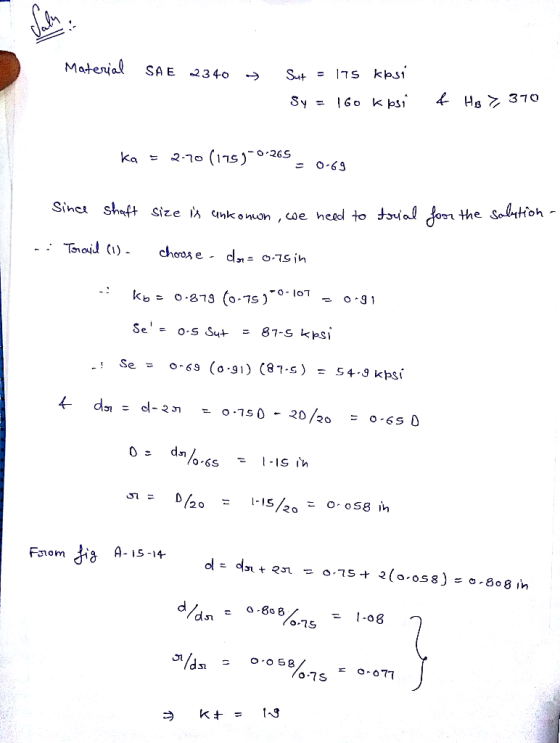
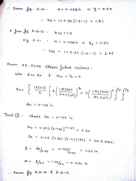
 The section of shaft shown in the figure is to be designed to approximate relative sizes of d 0.75D and r- D/20 with diameter d conforming to that of standard rolling-bearing bore sizes. The shaft is to be made of SAE 2340 steel, heat-treated to obtain minimum strengths in the shoulder area of 175 kpsi ultimate tensile strength and 160 kpsi yield strength with a Brinell hardness not less than 370. At the shoulder the shaft is subjected to a...
Problems 1. (Subtotal: 21 points) A steady torque of 1500 Ibf in is transmitted by a...
 Problems 1. (Subtotal: 21 points) A steady torque of 1500 Ibf in is transmitted by a machined shaft made of steel with an ultimate tensile strength of 100 kpsi. The transverse cross section at the location of a shoulder against which a gear sits is subjected to a bending moment which is a sinusoidal function of time with a maximum of 800 lbf-in. Furthermore, this cross section is the location for the maximum von Mises stress. The smaller diameter at...
The shaft shown in the figure is driven by a gear at the right keyway, drives...
 The shaft shown in the figure is driven by a gear at the right keyway, drives a fan at the left keyway, and is supported by two deep-groove ball bearings at locations A and B. The shaft is made from AISI 1045 cold-drawn steel. At steady- state speed, the gear transmits a radial load of 300 lbf and a tangential load of 700 lbf at a pitch diameter of 8 in. Assume that the weight and axial load of the...
QUESTION 10 The shaft shown in the figure is driven by a gear at the right...
 QUESTION 10 The shaft shown in the figure is driven by a gear at the right keyway, drives a fan at the left keyway, and is supported by two deep-groove ball bearings at locations A and B. The shaft is made from AISI 1045 cold-drawn steel. At steady-state speed, the gear transmits a radial load of 300 lbf and a tangential load of 700 lbf at a pitch diameter of 8 in. Assume that the weight and axial load of...
The shaft shown in the figure is driven by a gear at the right keyway, drives...
 The shaft shown in the figure is driven by a gear at the right keyway, drives a fan at the left keyway, and is supported by two deep-groove ball bearings at locations A and B. The shaft is made from AISI 1045 cold-drawn steel. At steady-state speed, the gear transmits a radial load of 300 lbf and a tangential load of 700 lbf at a pitch diameter of 8 in. Assume that the weight and axial load of the fan...
Oestion-2 The rotating shaft shown in the figure is machined from S- 570Mpa. It is subjected...
 Oestion-2 The rotating shaft shown in the figure is machined from S- 570Mpa. It is subjected to a fluctuating load varyýing om Note all length dimensions are in mm) Find the reactions (Ri and Ra) at ure is machined from AISI 1020 CD steel with S670Mpa und varying from 0 to 7000N a) shaft (at 180mm from left). upports and maximum bending moment Miman at most critical point on and b) Find the alternating g amplitude (σ.), midrange (σ )...
The rotating solid steel shaft is simply supported by bearings at points B and C and is driven by gear (not shown) which meshes with the spur gear at D
 The rotating solid steel shaft is simply supported by bearings at points B and C and is driven by gear (not shown) which meshes with the spur gear at D, which has a 150-mm pitch diameter. The force F from the drive gear acts at a pressure angle of 20". The shaft transmits a torque to point A of TA = 340 N.m. The shaft is machined from steel with Sy= 420 MPa and Sut = 560 MPa. The fatigue...
2. (8 points) A solid shaft shown below is loaded in bending and torsion with steady...
 2. (8 points) A solid shaft shown below is loaded in bending and torsion with steady rotation. The total bending moment and torque diagrams are also given. The selected shaft steel material has an ultimate tensile strength Sut = 68kpsi, initial yield stress Sy = 57kpsi, and fully corrected factors for endurance limit, kakykekakek, = 0.60. (a) (6 points) Determine the factor of safety at point D of the shaft using DE-ASME Elliptic criterion. Assume K, = 1.8 and Kfs...
 The section of shaft shown in the figure is to be designed to approximate relative sizes of d 0.75D and r- D/20 with diameter d conforming to that of standard rolling-bearing bore sizes. The shaft is to be made of SAE 2340 steel, heat-treated to obtain minimum strengths in the shoulder area of 175 kpsi ultimate tensile strength and 160 kpsi yield strength with a Brinell hardness not less than 370. At the shoulder the shaft is subjected to a...
 Problems 1. (Subtotal: 21 points) A steady torque of 1500 Ibf in is transmitted by a machined shaft made of steel with an ultimate tensile strength of 100 kpsi. The transverse cross section at the location of a shoulder against which a gear sits is subjected to a bending moment which is a sinusoidal function of time with a maximum of 800 lbf-in. Furthermore, this cross section is the location for the maximum von Mises stress. The smaller diameter at...
 The shaft shown in the figure is driven by a gear at the right keyway, drives a fan at the left keyway, and is supported by two deep-groove ball bearings at locations A and B. The shaft is made from AISI 1045 cold-drawn steel. At steady- state speed, the gear transmits a radial load of 300 lbf and a tangential load of 700 lbf at a pitch diameter of 8 in. Assume that the weight and axial load of the...
 QUESTION 10 The shaft shown in the figure is driven by a gear at the right keyway, drives a fan at the left keyway, and is supported by two deep-groove ball bearings at locations A and B. The shaft is made from AISI 1045 cold-drawn steel. At steady-state speed, the gear transmits a radial load of 300 lbf and a tangential load of 700 lbf at a pitch diameter of 8 in. Assume that the weight and axial load of...
 The shaft shown in the figure is driven by a gear at the right keyway, drives a fan at the left keyway, and is supported by two deep-groove ball bearings at locations A and B. The shaft is made from AISI 1045 cold-drawn steel. At steady-state speed, the gear transmits a radial load of 300 lbf and a tangential load of 700 lbf at a pitch diameter of 8 in. Assume that the weight and axial load of the fan...
 The shaft shown in the figure is driven by a gear at the right keyway, drives a fan at the left keyway, and is supported by two deep-groove ball bearings at locations A and B. The shaft is made from AISI 1045 cold-drawn steel. At steady-state speed, the gear transmits a radial load of 300 lbf and a tangential load of 700 lbf at a pitch diameter of 8 in. Assume that the weight and axial load of the fan...
 Oestion-2 The rotating shaft shown in the figure is machined from S- 570Mpa. It is subjected to a fluctuating load varyýing om Note all length dimensions are in mm) Find the reactions (Ri and Ra) at ure is machined from AISI 1020 CD steel with S670Mpa und varying from 0 to 7000N a) shaft (at 180mm from left). upports and maximum bending moment Miman at most critical point on and b) Find the alternating g amplitude (σ.), midrange (σ )...
 2. (8 points) A solid shaft shown below is loaded in bending and torsion with steady rotation. The total bending moment and torque diagrams are also given. The selected shaft steel material has an ultimate tensile strength Sut = 68kpsi, initial yield stress Sy = 57kpsi, and fully corrected factors for endurance limit, kakykekakek, = 0.60. (a) (6 points) Determine the factor of safety at point D of the shaft using DE-ASME Elliptic criterion. Assume K, = 1.8 and Kfs...
Most questions answered within 3 hours.
-
Little’s Law: Val d’Costa is a world famous ski village in the
French Alps. Because of...
asked 1 minute ago -
Find the absolute error D for the calculation if A + B/C=D A=
9.4 +/- 0.4...
asked 14 minutes ago -
New Air Heating and Cooling, manufactures furnaces and central
air units. The company pride itself on...
asked 28 minutes ago -
A coach uses a new technique to train gymnasts. Seven
gymnasts were randomly selected and their...
asked 2 hours ago -
While rotating the tires on your car you notice a rock [mass =
0.1 Kg] stuck...
asked 4 hours ago -
Using MARS simulator, write MIPS programs according to
the following scenarios: Receive a positive integer number...
asked 6 hours ago -
An object in front of a concave mirror has a real image that is
11.5 cm...
asked 6 hours ago -
Consider the reaction, C3 H8 + O2 --> CO2 + H2O. How many
moles of O2...
asked 8 hours ago -
You and your opponent both roll a fair die. If you both roll the
same number,...
asked 8 hours ago -
In a study of the accuracy of fast food drive-through orders,
Restaurant A had 257 accurate...
asked 8 hours ago -
Identify and describe in detail the four categories of
institutions that could be included in a...
asked 8 hours ago -
In python
class Customer:
def __init__(self, customer_id, last_name, first_name, phone_number, address):
self._customer_id = int(customer_id)
self._last_name =...
asked 8 hours ago