
Homework Answers


If this is helpful, please UPVOTE. Thank you !!
Add Answer to:
QUESTION 10 The shaft shown in the figure is driven by a gear at the right...
The shaft shown in the figure is driven by a gear at the right keyway, drives...
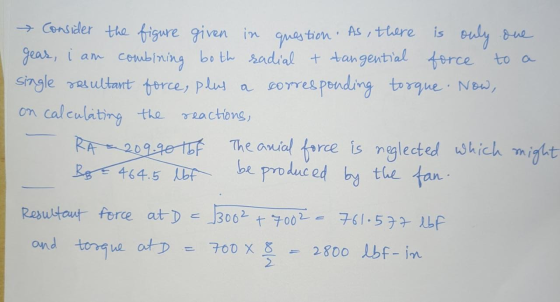
 The shaft shown in the figure is driven by a gear at the right keyway, drives a fan at the left keyway, and is supported by two deep-groove ball bearings at locations A and B. The shaft is made from AISI 1045 cold-drawn steel. At steady-state speed, the gear transmits a radial load of 300 lbf and a tangential load of 700 lbf at a pitch diameter of 8 in. Assume that the weight and axial load of the fan...
The shaft shown in the figure is driven by a gear at the right keyway, drives...
 The shaft shown in the figure is driven by a gear at the right keyway, drives a fan at the left keyway, and is supported by two deep-groove ball bearings at locations A and B. The shaft is made from AISI 1045 cold-drawn steel. At steady- state speed, the gear transmits a radial load of 300 lbf and a tangential load of 700 lbf at a pitch diameter of 8 in. Assume that the weight and axial load of the...
2. (8 points) A solid shaft shown below is loaded in bending and torsion with steady...
 2. (8 points) A solid shaft shown below is loaded in bending and torsion with steady rotation. The total bending moment and torque diagrams are also given. The selected shaft steel material has an ultimate tensile strength Sut = 68kpsi, initial yield stress Sy = 57kpsi, and fully corrected factors for endurance limit, kakykekakek, = 0.60. (a) (6 points) Determine the factor of safety at point D of the shaft using DE-ASME Elliptic criterion. Assume K, = 1.8 and Kfs...
2.The shaft shown in the figure is driven by a gear at the right keyways, drive...
 2.The shaft shown in the figure is driven by a gear at the right keyways, drive a fan at eh left keyways, and supported by two deep grove ball bearings. The shaft is made of AISI 1020 cold- drawn steel. At steady state speed, the gear transmits a radial load of 230 Ibf and a tangential load of 633 Ibf at pitch diameter of 8 inch. Determine fatigue factor of safety at any potentially critical locations using the DE-Gerber failure...
A gear reduction unit uses the countershaft shown A gear A receives power from another gear...
 A gear reduction unit uses the countershaft shown A gear A receives power from another gear with the transmitted force FA applied at the 20° pressure angle as shown. The power is transmitted through the shaft and delivered through gear B through a transmitted force Fa at the pressure angle shown 16 in in in 20° 1.25-in dia (a)Determine the minimum factor of safety for fatigue based on infinite life, using the modified Goodman criterion Gear A 20-in dia. (b)Determine...
doesn't need any extra information, everything is in there indi 2.. In the figure shown, shaft...
 doesn't need any extra information, everything is in
there
indi 2.. In the figure shown, shaft A, made of AISI 1020 hot-rolled steel, is welded to a fixed support and is subjected to loading by equal and opposite forces F via shaft B. A theoretical stress-concentration factor Kts of 1.6 is induced in the shaft by the -in weld fillet. The length of shaft A from the fixed support to the connection at shaft B is 2 ft. The load...
doesn't need any extra information, everything is in
there
indi 2.. In the figure shown, shaft A, made of AISI 1020 hot-rolled steel, is welded to a fixed support and is subjected to loading by equal and opposite forces F via shaft B. A theoretical stress-concentration factor Kts of 1.6 is induced in the shaft by the -in weld fillet. The length of shaft A from the fixed support to the connection at shaft B is 2 ft. The load...
A rotating step shaft is loaded as shown, where the forces FA and FB are constant...
 A rotating step shaft is loaded as shown, where the forces FA and FB are constant at 600 lbf and 300 lbf, respectively, and the torque T alternates from 0 to 1800 lbf in. The shaft is to be considered simply supported at points 0 and C, and is made of AISI 1045 CD steel with a fully corrected endurance limit of Se = 40 kpsi. Let Ki = 2.1 and K = 1.7. For a design factor of 2.5...
A rotating step shaft is loaded as shown, where the forces FA and FB are constant...
 A rotating step shaft is loaded as shown, where the forces FA and FB are constant at 600 lbf and 300 lbf, respectively, and the torque T alternates from 0 to 1800 lbf . in. The shaft is to be considered simply supported at points and C, and is made of AISI 1045 CD steel with a fully corrected endurance limit of Se = 40 kpsi. Let Kg = 2.1 and K = 1.7. For a design factor of 2.5...
The section of shaft shown in the figure is to be designed to approximate relative sizes of d 0.7...
 The section of shaft shown in the figure is to be designed to approximate relative sizes of d 0.75D and r- D/20 with diameter d conforming to that of standard rolling-bearing bore sizes. The shaft is to be made of SAE 2340 steel, heat-treated to obtain minimum strengths in the shoulder area of 175 kpsi ultimate tensile strength and 160 kpsi yield strength with a Brinell hardness not less than 370. At the shoulder the shaft is subjected to a...
 The shaft shown in the figure is driven by a gear at the right keyway, drives a fan at the left keyway, and is supported by two deep-groove ball bearings at locations A and B. The shaft is made from AISI 1045 cold-drawn steel. At steady-state speed, the gear transmits a radial load of 300 lbf and a tangential load of 700 lbf at a pitch diameter of 8 in. Assume that the weight and axial load of the fan...
 The shaft shown in the figure is driven by a gear at the right keyway, drives a fan at the left keyway, and is supported by two deep-groove ball bearings at locations A and B. The shaft is made from AISI 1045 cold-drawn steel. At steady-state speed, the gear transmits a radial load of 300 lbf and a tangential load of 700 lbf at a pitch diameter of 8 in. Assume that the weight and axial load of the fan...
 The shaft shown in the figure is driven by a gear at the right keyway, drives a fan at the left keyway, and is supported by two deep-groove ball bearings at locations A and B. The shaft is made from AISI 1045 cold-drawn steel. At steady- state speed, the gear transmits a radial load of 300 lbf and a tangential load of 700 lbf at a pitch diameter of 8 in. Assume that the weight and axial load of the...
 2. (8 points) A solid shaft shown below is loaded in bending and torsion with steady rotation. The total bending moment and torque diagrams are also given. The selected shaft steel material has an ultimate tensile strength Sut = 68kpsi, initial yield stress Sy = 57kpsi, and fully corrected factors for endurance limit, kakykekakek, = 0.60. (a) (6 points) Determine the factor of safety at point D of the shaft using DE-ASME Elliptic criterion. Assume K, = 1.8 and Kfs...
 2.The shaft shown in the figure is driven by a gear at the right keyways, drive a fan at eh left keyways, and supported by two deep grove ball bearings. The shaft is made of AISI 1020 cold- drawn steel. At steady state speed, the gear transmits a radial load of 230 Ibf and a tangential load of 633 Ibf at pitch diameter of 8 inch. Determine fatigue factor of safety at any potentially critical locations using the DE-Gerber failure...
 A gear reduction unit uses the countershaft shown A gear A receives power from another gear with the transmitted force FA applied at the 20° pressure angle as shown. The power is transmitted through the shaft and delivered through gear B through a transmitted force Fa at the pressure angle shown 16 in in in 20° 1.25-in dia (a)Determine the minimum factor of safety for fatigue based on infinite life, using the modified Goodman criterion Gear A 20-in dia. (b)Determine...
 doesn't need any extra information, everything is in
there
indi 2.. In the figure shown, shaft A, made of AISI 1020 hot-rolled steel, is welded to a fixed support and is subjected to loading by equal and opposite forces F via shaft B. A theoretical stress-concentration factor Kts of 1.6 is induced in the shaft by the -in weld fillet. The length of shaft A from the fixed support to the connection at shaft B is 2 ft. The load...
doesn't need any extra information, everything is in
there
indi 2.. In the figure shown, shaft A, made of AISI 1020 hot-rolled steel, is welded to a fixed support and is subjected to loading by equal and opposite forces F via shaft B. A theoretical stress-concentration factor Kts of 1.6 is induced in the shaft by the -in weld fillet. The length of shaft A from the fixed support to the connection at shaft B is 2 ft. The load...
 A rotating step shaft is loaded as shown, where the forces FA and FB are constant at 600 lbf and 300 lbf, respectively, and the torque T alternates from 0 to 1800 lbf in. The shaft is to be considered simply supported at points 0 and C, and is made of AISI 1045 CD steel with a fully corrected endurance limit of Se = 40 kpsi. Let Ki = 2.1 and K = 1.7. For a design factor of 2.5...
 A rotating step shaft is loaded as shown, where the forces FA and FB are constant at 600 lbf and 300 lbf, respectively, and the torque T alternates from 0 to 1800 lbf . in. The shaft is to be considered simply supported at points and C, and is made of AISI 1045 CD steel with a fully corrected endurance limit of Se = 40 kpsi. Let Kg = 2.1 and K = 1.7. For a design factor of 2.5...
 The section of shaft shown in the figure is to be designed to approximate relative sizes of d 0.75D and r- D/20 with diameter d conforming to that of standard rolling-bearing bore sizes. The shaft is to be made of SAE 2340 steel, heat-treated to obtain minimum strengths in the shoulder area of 175 kpsi ultimate tensile strength and 160 kpsi yield strength with a Brinell hardness not less than 370. At the shoulder the shaft is subjected to a...
Most questions answered within 3 hours.
-
The extent to which assets are financed by borrowed funds and
other liabilities is indicated by:...
asked 36 minutes ago -
Explain in detail
Germany is the fifth largest economy
explain what goods and services Germany specializes...
asked 51 minutes ago -
The density of platinum is 21.45 g/mL. If a cube of platinum
with a mass of...
asked 56 minutes ago -
Accounts Receivable
Sales
A/R Posting
Extended Sales Invoice
Packing Slip
Compare invoice to packing slip 2...
asked 59 minutes ago -
Michaella, age 23, is a full-time law student and is claimed by
her parents as a...
asked 1 hour ago -
Why are polymers not typically casted into products?
asked 1 hour ago -
When rolling a die 129 times, what is the probability of rolling
a 6 no more...
asked 1 hour ago -
4. A call option currently sells for $7.75. It has a strike
price of $85 and...
asked 1 hour ago -
1.
You need to prepare 10.0 liters of an acid aqueous solution with a
pH of...
asked 1 hour ago -
Along an aggregate supply curve, if the level of output is less
than the natural level...
asked 1 hour ago -
By 2025, annual consumption in emerging markets will total $30
trillion and contribute more than ________...
asked 1 hour ago -
At what point does reformation cease to be a viable option for
those who are oppressed...
asked 1 hour ago