PLEASE HELP IMMEDIATELY

5) The amplitude of current through C2 flowing downward. (Unit: A) Submit Answer Tries o/:3 6) The phase of current through through C2 flowing downward. (Unit: rad) Submit Answer Tries o/3
Homework Answers
Add Answer to:
R2 R3 R1 C1 C2 S2 51 In the circuit, the signal frequency f = 1.2 MHz, R1=9 Ohm, R2 = 8 Ohm, R3 =...
answer using Matlab or Octave please Fig.ACNodal2 In the circuit, R1-8 Ohm, R2 = 10 Ohm,...
 answer using Matlab or Octave please
Fig.ACNodal2 In the circuit, R1-8 Ohm, R2 = 10 Ohm, R3 - 4 Ohm, the reactances of inductors and capacitor are XL1=4 Ohm, XL21 Ohm, XC1=2 Ohm; voltage source amplitude and phase are 11 V and O rad. Using nodal analysis, find the following 1) The amplitude of the potential at the top lead of inductor L1. (Unit: V) Submit Answer Tries 0/3 2) The phase of of the potential at the top lead...
answer using Matlab or Octave please
Fig.ACNodal2 In the circuit, R1-8 Ohm, R2 = 10 Ohm, R3 - 4 Ohm, the reactances of inductors and capacitor are XL1=4 Ohm, XL21 Ohm, XC1=2 Ohm; voltage source amplitude and phase are 11 V and O rad. Using nodal analysis, find the following 1) The amplitude of the potential at the top lead of inductor L1. (Unit: V) Submit Answer Tries 0/3 2) The phase of of the potential at the top lead...
PLEASE DO NOT ANSWER UNLESS YOU ARE %100 SURE Fig. ACNodal2 In the circuit, Ri=6 Ohm,...
 PLEASE DO NOT ANSWER UNLESS
YOU ARE %100 SURE
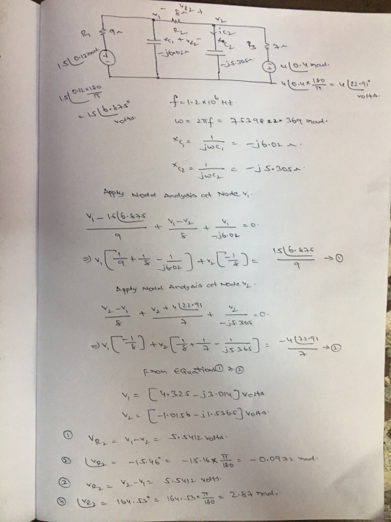
Fig. ACNodal2 In the circuit, Ri=6 Ohm, R2 = 9 Ohm, R3 = 4 Ohm, the reactances of inductors and capacitor are XL1=7 Ohm, XL2=3.5 Ohm, XCI=4.2 Ohm; voltage source amplitude and phase are 11 V and 0.12 rad. Using nodal analysis, find the following 1) The amplitude of the potential at the top lead of inductor L1. (Unit: V) 7.350 V Computer's answer now shown above. You are correct. Previous...
PLEASE DO NOT ANSWER UNLESS
YOU ARE %100 SURE
Fig. ACNodal2 In the circuit, Ri=6 Ohm, R2 = 9 Ohm, R3 = 4 Ohm, the reactances of inductors and capacitor are XL1=7 Ohm, XL2=3.5 Ohm, XCI=4.2 Ohm; voltage source amplitude and phase are 11 V and 0.12 rad. Using nodal analysis, find the following 1) The amplitude of the potential at the top lead of inductor L1. (Unit: V) 7.350 V Computer's answer now shown above. You are correct. Previous...
L1 s] CI ?2 s2 In the circuit, the amplitude and phase of the voltage source...
 L1 s] CI ?2 s2 In the circuit, the amplitude and phase of the voltage source Vs1 are 120 V and 0.4 rad, those of the voltage source Vs2 are 230 V and 0.5 rad, the voltage frequency is 20 kHz; 36 mH, L2 20 mH, C1 2.5 nF R1-3 kOhm, R2 7 kOhm, R36 kOhm, L1 Find the impedance of inductor L1 Real part of impedance (Ohm) Submit Answer Tries 0/3 Impaginary part of impedance (Ohm): Submit Answer Tries...
In the circuit, R1=50 Ohm, R2 = 36 Ohm, the reactance of the inductor L1 is...
 In the circuit, R1=50 Ohm, R2 = 36 Ohm, the reactance of the
inductor L1 is XL1=15 Ohm, the absolute value of the capacitor C1
reactance, XC1=98.8 Ohm.
The voltage source VS amplitude and phase are VSm=20 V and VSph=0.8
rad.
L1C1 om R2 VSm ZVSph ~ R13 R2 In the circuit, R1=50 Ohm, R2 = 36 Ohm, the reactance of the inductor Li is XL1=15 Ohm, the absolute value of the capacitor C1 reactance, XC1=98.8 Ohm. The voltage source...
In the circuit, R1=50 Ohm, R2 = 36 Ohm, the reactance of the
inductor L1 is XL1=15 Ohm, the absolute value of the capacitor C1
reactance, XC1=98.8 Ohm.
The voltage source VS amplitude and phase are VSm=20 V and VSph=0.8
rad.
L1C1 om R2 VSm ZVSph ~ R13 R2 In the circuit, R1=50 Ohm, R2 = 36 Ohm, the reactance of the inductor Li is XL1=15 Ohm, the absolute value of the capacitor C1 reactance, XC1=98.8 Ohm. The voltage source...
Problem 06 СХС VS1 = VS1m 20s1 VS2 = VS2M 202 In the circuit, R=6 Ohm,...
 Problem 06 СХС VS1 = VS1m 20s1 VS2 = VS2M 202 In the circuit, R=6 Ohm, XL=3 Ohm, XC=9 Ohm; VS1 amplitude and phase are 12 V and O rad, VS2 amplitude and phase are 45 V and 0.9 rad. Using MESH Analysis, find the following 1a) The amplitude of the current through the resistor R flowing from left to right. (Unit: A) Submit Answer Tries 0/3 1b) The phase of the current through the resistor R flowing from left...
R2 R, Q2. In the above circuit, Vs1 = 11 V, Vs2 = 22 V, R1...
 R2 R, Q2. In the above circuit, Vs1 = 11 V, Vs2 = 22 V, R1 = 4 Ohm, R2 = 9 Ohm, R3 = 5.5 Ohm, R4 = 5 Ohm, R5 = 2.5 Ohm, R6 = 6 Ohm. B. Using mesh analysis, answer the following questions (Q2.2) Find the current through the resistor R1 in the direction from left to right. (Unit: A) Submit Answer Tries 0/3 (Q2.3) Find the current through the resistor R2 in the direction from...
What is the phase of the current through L1 flowing left to right? (unit: rad) I...
 What is the phase of the current through L1 flowing
left to right? (unit: rad)
I got every part right, including the amplitude
through L1, correct, but the phase is wrong. If you could do it in
MATLAB that'd be helpful so I can see where I messed up
Problem 02 C1 - m Vs1 ) C2 In the circuit, the amplitude and phase of the voltage and current sources are: Vs1: 8 V and 0.05 rad; Is1: 3 A...
What is the phase of the current through L1 flowing
left to right? (unit: rad)
I got every part right, including the amplitude
through L1, correct, but the phase is wrong. If you could do it in
MATLAB that'd be helpful so I can see where I messed up
Problem 02 C1 - m Vs1 ) C2 In the circuit, the amplitude and phase of the voltage and current sources are: Vs1: 8 V and 0.05 rad; Is1: 3 A...
In the circuit, Vs1 = 10.5 V, Is2 = 0.45 A, R1 = 37 Ohm, R2...
 In the circuit, Vs1 = 10.5 V, Is2 = 0.45 A, R1 = 37 Ohm, R2 = 19
Ohm, R3 = 36 Ohm, R4 = 26 Ohm.
Solve the obtained equations and find the following
currents.
1) Find the current through R1 flowing from left to right. (Unit:
A)
2) Find the current through R2 flowing downwards. (Unit: A)
3) Find the current through R3 flowing from left to right.
(Unit: A)
RI R3 4 3
In the circuit, Vs1 = 10.5 V, Is2 = 0.45 A, R1 = 37 Ohm, R2 = 19
Ohm, R3 = 36 Ohm, R4 = 26 Ohm.
Solve the obtained equations and find the following
currents.
1) Find the current through R1 flowing from left to right. (Unit:
A)
2) Find the current through R2 flowing downwards. (Unit: A)
3) Find the current through R3 flowing from left to right.
(Unit: A)
RI R3 4 3
Ri Vs S1 Q2. In the circuit, Vs 1 = 80 V, R1 = 4 Ohm,...
 Ri Vs S1 Q2. In the circuit, Vs 1 = 80 V, R1 = 4 Ohm, R2 = 28 Ohm, R3 = 94 Ohm, R4 = 8 Ohm and R5 = 27 Ohm. 1) Find the current through R1 flowing left to right. (Unit: A) Submit Answer Tries 0/5 2)Find the current through R2 flowing downwards. (Unit: A) Submit Answer Tries 0/3 3) Find the current through R3 flowing left to right. (Unit: A) Submit Answer Tries 0/3 4) Find...
Is1 2 R2 R1 Is2 R3 Vsl In the circuit, Vsi-24.8 V, Is1-2.1 A, 1s2-2.7 A,...
 Is1 2 R2 R1 Is2 R3 Vsl In the circuit, Vsi-24.8 V, Is1-2.1 A, 1s2-2.7 A, R1-8 Ohm, R2-10 Ohm, R3-8 Ohm Assume that the nodes-1" and "2" potentials are labeled as ℉1" and "F2" correspondingly. Using the notations of the ircuit diagram above (case sensitivel), wite the nodal equations for the Gircuit keeping all the terms on the left-hand side (LHS), so that the equation appears as LHS -0" Enter the left-hand side of nodal equation for the node...
 answer using Matlab or Octave please
Fig.ACNodal2 In the circuit, R1-8 Ohm, R2 = 10 Ohm, R3 - 4 Ohm, the reactances of inductors and capacitor are XL1=4 Ohm, XL21 Ohm, XC1=2 Ohm; voltage source amplitude and phase are 11 V and O rad. Using nodal analysis, find the following 1) The amplitude of the potential at the top lead of inductor L1. (Unit: V) Submit Answer Tries 0/3 2) The phase of of the potential at the top lead...
answer using Matlab or Octave please
Fig.ACNodal2 In the circuit, R1-8 Ohm, R2 = 10 Ohm, R3 - 4 Ohm, the reactances of inductors and capacitor are XL1=4 Ohm, XL21 Ohm, XC1=2 Ohm; voltage source amplitude and phase are 11 V and O rad. Using nodal analysis, find the following 1) The amplitude of the potential at the top lead of inductor L1. (Unit: V) Submit Answer Tries 0/3 2) The phase of of the potential at the top lead...
 PLEASE DO NOT ANSWER UNLESS
YOU ARE %100 SURE
Fig. ACNodal2 In the circuit, Ri=6 Ohm, R2 = 9 Ohm, R3 = 4 Ohm, the reactances of inductors and capacitor are XL1=7 Ohm, XL2=3.5 Ohm, XCI=4.2 Ohm; voltage source amplitude and phase are 11 V and 0.12 rad. Using nodal analysis, find the following 1) The amplitude of the potential at the top lead of inductor L1. (Unit: V) 7.350 V Computer's answer now shown above. You are correct. Previous...
PLEASE DO NOT ANSWER UNLESS
YOU ARE %100 SURE
Fig. ACNodal2 In the circuit, Ri=6 Ohm, R2 = 9 Ohm, R3 = 4 Ohm, the reactances of inductors and capacitor are XL1=7 Ohm, XL2=3.5 Ohm, XCI=4.2 Ohm; voltage source amplitude and phase are 11 V and 0.12 rad. Using nodal analysis, find the following 1) The amplitude of the potential at the top lead of inductor L1. (Unit: V) 7.350 V Computer's answer now shown above. You are correct. Previous...
 L1 s] CI ?2 s2 In the circuit, the amplitude and phase of the voltage source Vs1 are 120 V and 0.4 rad, those of the voltage source Vs2 are 230 V and 0.5 rad, the voltage frequency is 20 kHz; 36 mH, L2 20 mH, C1 2.5 nF R1-3 kOhm, R2 7 kOhm, R36 kOhm, L1 Find the impedance of inductor L1 Real part of impedance (Ohm) Submit Answer Tries 0/3 Impaginary part of impedance (Ohm): Submit Answer Tries...
 In the circuit, R1=50 Ohm, R2 = 36 Ohm, the reactance of the
inductor L1 is XL1=15 Ohm, the absolute value of the capacitor C1
reactance, XC1=98.8 Ohm.
The voltage source VS amplitude and phase are VSm=20 V and VSph=0.8
rad.
L1C1 om R2 VSm ZVSph ~ R13 R2 In the circuit, R1=50 Ohm, R2 = 36 Ohm, the reactance of the inductor Li is XL1=15 Ohm, the absolute value of the capacitor C1 reactance, XC1=98.8 Ohm. The voltage source...
In the circuit, R1=50 Ohm, R2 = 36 Ohm, the reactance of the
inductor L1 is XL1=15 Ohm, the absolute value of the capacitor C1
reactance, XC1=98.8 Ohm.
The voltage source VS amplitude and phase are VSm=20 V and VSph=0.8
rad.
L1C1 om R2 VSm ZVSph ~ R13 R2 In the circuit, R1=50 Ohm, R2 = 36 Ohm, the reactance of the inductor Li is XL1=15 Ohm, the absolute value of the capacitor C1 reactance, XC1=98.8 Ohm. The voltage source...
 Problem 06 СХС VS1 = VS1m 20s1 VS2 = VS2M 202 In the circuit, R=6 Ohm, XL=3 Ohm, XC=9 Ohm; VS1 amplitude and phase are 12 V and O rad, VS2 amplitude and phase are 45 V and 0.9 rad. Using MESH Analysis, find the following 1a) The amplitude of the current through the resistor R flowing from left to right. (Unit: A) Submit Answer Tries 0/3 1b) The phase of the current through the resistor R flowing from left...
 R2 R, Q2. In the above circuit, Vs1 = 11 V, Vs2 = 22 V, R1 = 4 Ohm, R2 = 9 Ohm, R3 = 5.5 Ohm, R4 = 5 Ohm, R5 = 2.5 Ohm, R6 = 6 Ohm. B. Using mesh analysis, answer the following questions (Q2.2) Find the current through the resistor R1 in the direction from left to right. (Unit: A) Submit Answer Tries 0/3 (Q2.3) Find the current through the resistor R2 in the direction from...
 What is the phase of the current through L1 flowing
left to right? (unit: rad)
I got every part right, including the amplitude
through L1, correct, but the phase is wrong. If you could do it in
MATLAB that'd be helpful so I can see where I messed up
Problem 02 C1 - m Vs1 ) C2 In the circuit, the amplitude and phase of the voltage and current sources are: Vs1: 8 V and 0.05 rad; Is1: 3 A...
What is the phase of the current through L1 flowing
left to right? (unit: rad)
I got every part right, including the amplitude
through L1, correct, but the phase is wrong. If you could do it in
MATLAB that'd be helpful so I can see where I messed up
Problem 02 C1 - m Vs1 ) C2 In the circuit, the amplitude and phase of the voltage and current sources are: Vs1: 8 V and 0.05 rad; Is1: 3 A...
 In the circuit, Vs1 = 10.5 V, Is2 = 0.45 A, R1 = 37 Ohm, R2 = 19
Ohm, R3 = 36 Ohm, R4 = 26 Ohm.
Solve the obtained equations and find the following
currents.
1) Find the current through R1 flowing from left to right. (Unit:
A)
2) Find the current through R2 flowing downwards. (Unit: A)
3) Find the current through R3 flowing from left to right.
(Unit: A)
RI R3 4 3
In the circuit, Vs1 = 10.5 V, Is2 = 0.45 A, R1 = 37 Ohm, R2 = 19
Ohm, R3 = 36 Ohm, R4 = 26 Ohm.
Solve the obtained equations and find the following
currents.
1) Find the current through R1 flowing from left to right. (Unit:
A)
2) Find the current through R2 flowing downwards. (Unit: A)
3) Find the current through R3 flowing from left to right.
(Unit: A)
RI R3 4 3
 Ri Vs S1 Q2. In the circuit, Vs 1 = 80 V, R1 = 4 Ohm, R2 = 28 Ohm, R3 = 94 Ohm, R4 = 8 Ohm and R5 = 27 Ohm. 1) Find the current through R1 flowing left to right. (Unit: A) Submit Answer Tries 0/5 2)Find the current through R2 flowing downwards. (Unit: A) Submit Answer Tries 0/3 3) Find the current through R3 flowing left to right. (Unit: A) Submit Answer Tries 0/3 4) Find...
 Is1 2 R2 R1 Is2 R3 Vsl In the circuit, Vsi-24.8 V, Is1-2.1 A, 1s2-2.7 A, R1-8 Ohm, R2-10 Ohm, R3-8 Ohm Assume that the nodes-1" and "2" potentials are labeled as ℉1" and "F2" correspondingly. Using the notations of the ircuit diagram above (case sensitivel), wite the nodal equations for the Gircuit keeping all the terms on the left-hand side (LHS), so that the equation appears as LHS -0" Enter the left-hand side of nodal equation for the node...
Most questions answered within 3 hours.
-
Investor company owns 35% of investee company voting stock and
accounts for the investment under the...
asked 42 minutes ago -
The number of major faults on a randomly chosen 1 km stretch of
highway has a...
asked 1 hour ago -
Consider the competitive environment of Starbuck's, Progressive
Insurance, a manufacturing firm with low turnover, or a...
asked 1 hour ago -
3. Gains from trade
Consider two neighbouring island countries called Euphoria and
Contente. They each have...
asked 3 hours ago -
A business executive has the option to invest money in two
plans: Plan A guarantees that...
asked 6 hours ago -
Hello, can someone please help me answer this question?
How much heat is absorbed by a...
asked 6 hours ago -
. A marketing researcher conducted a survey of 25 shoppers
randomly selected at the local mall...
asked 6 hours ago -
Create an comprehensive response to the
following:
Antimicrobial agents work on a multitude of microbes (bacteria,...
asked 6 hours ago -
6.13 LAB: Step counter. Section 6.3.
A pedometer treats walking 2,000 steps as walking 1 mile....
asked 6 hours ago -
(14.2) A block of mass m = 10 kg riding on a frictionless
horizontal plane is...
asked 6 hours ago -
Use any search engine to search for articles about Starbucks
partnership with Tata Companies in India...
asked 6 hours ago -
Let’s say that for some reason Bank Excess Reserves suddenly
increase sharply. What effect would this...
asked 6 hours ago