Desgin


shaft CD through a set of bevel gears contacting at E on the gear of shaft CD iBs 1600j+3600k N. For shaft CD: (a) draw a free- in the supports (assume load), (b) perform a preliminary specification for the bearing set, assuming distribution data from body diagram and determine the reactions at C and D assuming also that bearing C carries the thrust tapered roller bearings at C and D. A bearing life of 10 revolutions percent combined reliability for manufacturer I. 1. Assuming bearings are available with K 1.5, find the required radial rating for each bearing. For this preliminary design, assume an application factor of one. 165 100 mm 75 mm 20 mm dia. 33 mm 100mm ←2S mm dia.
Homework Answers


Add Answer to:
0.2) Figure Q.2 shows a drive system in which a 20-hp electric motor drives separate output shaft...
Desgin 0.2) Figure Q.2 shows a drive system in which a 20-hp electric motor drives separate...
 Desgin
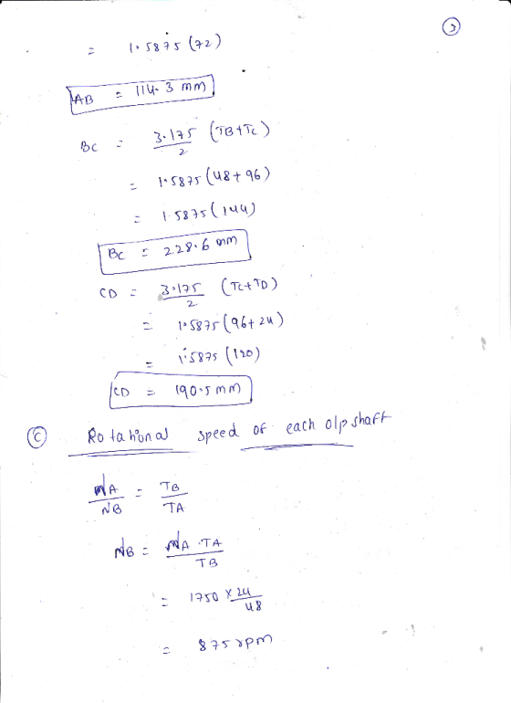
0.2) Figure Q.2 shows a drive system in which a 20-hp electric motor drives separate output shafts. Gear A is mounted on the motor shafit that has a rotational spoed or 1750 rpm clockwise. Gear A drives gear train consisting of…B,C,and D thr deliver power through the shafts on which they are mounted. All gears have a diametral pitch of Pa-8.The following data are given Power delivered by gears B, C, and D: Pa Numbers of teeth for all...
Desgin
0.2) Figure Q.2 shows a drive system in which a 20-hp electric motor drives separate output shafts. Gear A is mounted on the motor shafit that has a rotational spoed or 1750 rpm clockwise. Gear A drives gear train consisting of…B,C,and D thr deliver power through the shafts on which they are mounted. All gears have a diametral pitch of Pa-8.The following data are given Power delivered by gears B, C, and D: Pa Numbers of teeth for all...
q=154 Gear Drive motor Input A B D E Shaft Gear R - Gear S Output...
 q=154
Gear Drive motor Input A B D E Shaft Gear R - Gear S Output to crusher sis is etis olis Output to conveyor Gear C Gear A 101.6-mm dia. 304.8-mmdia. Gear E 63.5-mmdia. Pressure angle 20° for all gears Figure 1-3 A drive is designed for a system to crush coal and delivers it by conveyor to a railroad car. A drive is shown in Figure 1-3, which is designed for a system to crush coal and delivers...
q=154
Gear Drive motor Input A B D E Shaft Gear R - Gear S Output to crusher sis is etis olis Output to conveyor Gear C Gear A 101.6-mm dia. 304.8-mmdia. Gear E 63.5-mmdia. Pressure angle 20° for all gears Figure 1-3 A drive is designed for a system to crush coal and delivers it by conveyor to a railroad car. A drive is shown in Figure 1-3, which is designed for a system to crush coal and delivers...
Homework 6: The figure below shows a gear train where gear 1, on shaft a (input...
 Homework 6: The figure below shows a gear train where gear 1, on shaft a (input shaft), drives gear 2 with 32 teeth (denoted 32T) on shaft b, gear 3 (20T) also is on shaft b and drives gear 4 (507) on shaft c (output shaft). The pitch diameter of gears 1 and 2 are d = 24 mm and d = 48 mm. The center distance between gears 3 and 4 (distance between shafts b and c is 70mm....
The figure above shows two spur gears mounted on a shaft at A and C. This...
 The figure above shows two spur gears mounted on a shaft at A and C. This shaft gear assembly is supported on two pedestal bearings at D and Brespectively. These bearing supports act as simple supports. Neglect the weight of the shaft and the gears. The force on gear 1 is shown at an angle with respect to the vertical "y" axis and the force on gear 2 (Fc-1000 N) is shown at an angle with respect to the horizontal...
The motor shown in the figure supplies 14.0 kW at 1880 rpm at A. Shafts (1)...
 The motor shown in the figure supplies 14.0 kW at 1880 rpm at
A. Shafts (1) and (2) are each solid 26 mm diameter
shafts. Shaft (1) is made of an aluminum alloy [?G=26??GPa], and
shaft (2) is made of bronze [?G=45??GPa]. The shaft lengths are
L1=3.1m and L2=2.7m, respectively. Gear B has 55 teeth,
and gear C has 99 teeth. The bearings shown permit free
rotation of the shafts. Determine:
(a) the maximum shear stress produced in shafts
(1)...
The motor shown in the figure supplies 14.0 kW at 1880 rpm at
A. Shafts (1) and (2) are each solid 26 mm diameter
shafts. Shaft (1) is made of an aluminum alloy [?G=26??GPa], and
shaft (2) is made of bronze [?G=45??GPa]. The shaft lengths are
L1=3.1m and L2=2.7m, respectively. Gear B has 55 teeth,
and gear C has 99 teeth. The bearings shown permit free
rotation of the shafts. Determine:
(a) the maximum shear stress produced in shafts
(1)...
You are the designer and you have been asked to design a speed reducer (gearbox) that will take p...
 power = 3 kW
if need any more information please ask !!!
You are the designer and you have been asked to design a speed reducer (gearbox) that will take power from the shaft of an electric motor rotating at 1500 rpm and deliver it to a machine that is to operate at approximately at 200 rpm Assume that you have decided to use spur gears to transmit the power [A power equal to the last one digits of your...
power = 3 kW
if need any more information please ask !!!
You are the designer and you have been asked to design a speed reducer (gearbox) that will take power from the shaft of an electric motor rotating at 1500 rpm and deliver it to a machine that is to operate at approximately at 200 rpm Assume that you have decided to use spur gears to transmit the power [A power equal to the last one digits of your...
The figure shows a pair of shaft-mounted spur gears having a diametral pitch of 5 teeth/in with a...
 The figure shows a pair of shaft-mounted spur gears having a diametral pitch of 5 teeth/in with an 18-tooth 20° pinion driving a 50-tooth gear. The horsepower input is 31 maximum at 1.600 rev/min. Find the magnitude of the maximum forces acting on bearings A,B, C, and D 3 in 3 in RA RB = lbf lbf lbf lbf RD =
The figure shows a pair of shaft-mounted spur gears having a diametral pitch of 5 teeth/in with an 18-tooth...
The figure shows a pair of shaft-mounted spur gears having a diametral pitch of 5 teeth/in with an 18-tooth 20° pinion driving a 50-tooth gear. The horsepower input is 31 maximum at 1.600 rev/min. Find the magnitude of the maximum forces acting on bearings A,B, C, and D 3 in 3 in RA RB = lbf lbf lbf lbf RD =
The figure shows a pair of shaft-mounted spur gears having a diametral pitch of 5 teeth/in with an 18-tooth...
2. Gear dynamics. The gear train above is driven on the input shaft with a 0.5...
2. Gear dynamics. The gear train above is driven on the input shaft with a 0.5 hp electric motor. All of the gears have a diametral pitch of 8 teeth per inch. a) What are the diameters of Gears 1, 2, 3, and 4? b) What is the pitch-line velocity of Gear 1, in ft/min? c) Is the pitch-line velocity of Gear 2 the same as Gear 1? d) What is the pitch-line velocity of Gear 3 (and, therefore, Gear...
Problem 1 (25 Points) Two solid steel (6-80 GPa) shafts are connected by the gears shown. Shaft (1) has a diameter of 45 mm, and shaft (2) has an outside diameter of 55 mm and wall thickness 4 mm...
 Problem 1 (25 Points) Two solid steel (6-80 GPa) shafts are connected by the gears shown. Shaft (1) has a diameter of 45 mm, and shaft (2) has an outside diameter of 55 mm and wall thickness 4 mm. Assume that the bearings shown allow free rotation of the shafts. If a 400 N-m torque is applied at gear D, determine (a) the maximum shear stress magnitudes in each shaft. (b) the angles of twist ф, and ф (c) the...
1. Noise & Vibration Control of a Loaded Rotating Shaft: The motor drives a simply supported circ...
 1. Noise & Vibration Control of a Loaded Rotating Shaft: The motor drives a simply supported circular shaft of length L-4a, carrying three identical gears (mass of each m-100 kg), mounted on the shaft as shown. The shaft is made of steel (p-7700 kg/m, E-200 GPa) with a-0.50 m, and d-50 mm. Determine a safe motor size in Hertz (Hz) in order to avoid Gear Position 1 Node 1 2 Node 2 3 Node 3 Motor 3 Summary: Attach details...
 Desgin
0.2) Figure Q.2 shows a drive system in which a 20-hp electric motor drives separate output shafts. Gear A is mounted on the motor shafit that has a rotational spoed or 1750 rpm clockwise. Gear A drives gear train consisting of…B,C,and D thr deliver power through the shafts on which they are mounted. All gears have a diametral pitch of Pa-8.The following data are given Power delivered by gears B, C, and D: Pa Numbers of teeth for all...
Desgin
0.2) Figure Q.2 shows a drive system in which a 20-hp electric motor drives separate output shafts. Gear A is mounted on the motor shafit that has a rotational spoed or 1750 rpm clockwise. Gear A drives gear train consisting of…B,C,and D thr deliver power through the shafts on which they are mounted. All gears have a diametral pitch of Pa-8.The following data are given Power delivered by gears B, C, and D: Pa Numbers of teeth for all...
 q=154
Gear Drive motor Input A B D E Shaft Gear R - Gear S Output to crusher sis is etis olis Output to conveyor Gear C Gear A 101.6-mm dia. 304.8-mmdia. Gear E 63.5-mmdia. Pressure angle 20° for all gears Figure 1-3 A drive is designed for a system to crush coal and delivers it by conveyor to a railroad car. A drive is shown in Figure 1-3, which is designed for a system to crush coal and delivers...
q=154
Gear Drive motor Input A B D E Shaft Gear R - Gear S Output to crusher sis is etis olis Output to conveyor Gear C Gear A 101.6-mm dia. 304.8-mmdia. Gear E 63.5-mmdia. Pressure angle 20° for all gears Figure 1-3 A drive is designed for a system to crush coal and delivers it by conveyor to a railroad car. A drive is shown in Figure 1-3, which is designed for a system to crush coal and delivers...
 Homework 6: The figure below shows a gear train where gear 1, on shaft a (input shaft), drives gear 2 with 32 teeth (denoted 32T) on shaft b, gear 3 (20T) also is on shaft b and drives gear 4 (507) on shaft c (output shaft). The pitch diameter of gears 1 and 2 are d = 24 mm and d = 48 mm. The center distance between gears 3 and 4 (distance between shafts b and c is 70mm....
 The figure above shows two spur gears mounted on a shaft at A and C. This shaft gear assembly is supported on two pedestal bearings at D and Brespectively. These bearing supports act as simple supports. Neglect the weight of the shaft and the gears. The force on gear 1 is shown at an angle with respect to the vertical "y" axis and the force on gear 2 (Fc-1000 N) is shown at an angle with respect to the horizontal...
 The motor shown in the figure supplies 14.0 kW at 1880 rpm at
A. Shafts (1) and (2) are each solid 26 mm diameter
shafts. Shaft (1) is made of an aluminum alloy [?G=26??GPa], and
shaft (2) is made of bronze [?G=45??GPa]. The shaft lengths are
L1=3.1m and L2=2.7m, respectively. Gear B has 55 teeth,
and gear C has 99 teeth. The bearings shown permit free
rotation of the shafts. Determine:
(a) the maximum shear stress produced in shafts
(1)...
The motor shown in the figure supplies 14.0 kW at 1880 rpm at
A. Shafts (1) and (2) are each solid 26 mm diameter
shafts. Shaft (1) is made of an aluminum alloy [?G=26??GPa], and
shaft (2) is made of bronze [?G=45??GPa]. The shaft lengths are
L1=3.1m and L2=2.7m, respectively. Gear B has 55 teeth,
and gear C has 99 teeth. The bearings shown permit free
rotation of the shafts. Determine:
(a) the maximum shear stress produced in shafts
(1)...
 power = 3 kW
if need any more information please ask !!!
You are the designer and you have been asked to design a speed reducer (gearbox) that will take power from the shaft of an electric motor rotating at 1500 rpm and deliver it to a machine that is to operate at approximately at 200 rpm Assume that you have decided to use spur gears to transmit the power [A power equal to the last one digits of your...
power = 3 kW
if need any more information please ask !!!
You are the designer and you have been asked to design a speed reducer (gearbox) that will take power from the shaft of an electric motor rotating at 1500 rpm and deliver it to a machine that is to operate at approximately at 200 rpm Assume that you have decided to use spur gears to transmit the power [A power equal to the last one digits of your...
 The figure shows a pair of shaft-mounted spur gears having a diametral pitch of 5 teeth/in with an 18-tooth 20° pinion driving a 50-tooth gear. The horsepower input is 31 maximum at 1.600 rev/min. Find the magnitude of the maximum forces acting on bearings A,B, C, and D 3 in 3 in RA RB = lbf lbf lbf lbf RD =
The figure shows a pair of shaft-mounted spur gears having a diametral pitch of 5 teeth/in with an 18-tooth...
The figure shows a pair of shaft-mounted spur gears having a diametral pitch of 5 teeth/in with an 18-tooth 20° pinion driving a 50-tooth gear. The horsepower input is 31 maximum at 1.600 rev/min. Find the magnitude of the maximum forces acting on bearings A,B, C, and D 3 in 3 in RA RB = lbf lbf lbf lbf RD =
The figure shows a pair of shaft-mounted spur gears having a diametral pitch of 5 teeth/in with an 18-tooth...
 Problem 1 (25 Points) Two solid steel (6-80 GPa) shafts are connected by the gears shown. Shaft (1) has a diameter of 45 mm, and shaft (2) has an outside diameter of 55 mm and wall thickness 4 mm. Assume that the bearings shown allow free rotation of the shafts. If a 400 N-m torque is applied at gear D, determine (a) the maximum shear stress magnitudes in each shaft. (b) the angles of twist ф, and ф (c) the...
 1. Noise & Vibration Control of a Loaded Rotating Shaft: The motor drives a simply supported circular shaft of length L-4a, carrying three identical gears (mass of each m-100 kg), mounted on the shaft as shown. The shaft is made of steel (p-7700 kg/m, E-200 GPa) with a-0.50 m, and d-50 mm. Determine a safe motor size in Hertz (Hz) in order to avoid Gear Position 1 Node 1 2 Node 2 3 Node 3 Motor 3 Summary: Attach details...
Most questions answered within 3 hours.
-
1 Refer to the build-borrow-or-buy framework as a decision tree
for the Adidas company. Identify a...
asked 13 minutes ago -
Problem 2: The Problem of Social Cost. A Rancher and Farmer live
side-by-side to each other....
asked 1 hour ago -
a uniform bar of weight 40N is 4 meter long. weights
on 60N and 100N are...
asked 1 hour ago -
Define Diet counceling? What are the
responsibilities of a counselor?
asked 3 hours ago -
Hey im just confused about how to put the ' A angle n' and ' S...
asked 3 hours ago -
A short essay about the WSJ article on Oreo versus Hydrox.
asked 3 hours ago -
##8. A program contains the following function definition:
##def cube(num):
##return num * num * num...
asked 3 hours ago -
find the value z of a standard Normal variable that satisfies
each of the given conditions....
asked 3 hours ago -
"banana".find('z')
Out[22]: -1
why is this -1
python 3.7
asked 3 hours ago -
Ilegal Consideration Marna Balin was involved in two automobile
accidents in which she suffered severe injures.She...
asked 3 hours ago -
Walk through the operation of QuickSort when n = 7 and the input
array is A...
asked 3 hours ago -
Answer with True or False. Argue the answers
7) The circulation of field B on any...
asked 3 hours ago