
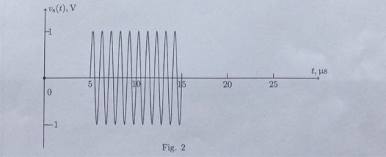
(h) assume that the impulse from Fig. 2 repeats every T = 20 us, and, using the Fourier analysis, acquire the output signal graph.
t us(t), V 1 t, us 20 25 Fig. 2
Homework Answers
Add Answer to:
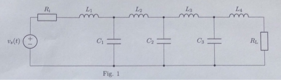
Ri し2 し3 し4 1 s(t) ( ± C3 RL 2 Fig. 1 (h) assume that the impulse from Fig. 2 repeats every ...
Ri し2 し3 し4 1 s(t) ( ± C3 RL 2 Fig. 1 (d) using the acquired AFR graph identify the type of ...
 please solve the question using Matlab, and provide Matlab
codes and graphs.
Ri し2 し3 し4 1 s(t) ( ± C3 RL 2 Fig. 1 (d) using the acquired AFR graph identify the type of the filter (Butterworth, Chebyshev of type I or II, or Elliptic / Cauer) and its order;
Ri し2 し3 し4 1 s(t) ( ± C3 RL 2 Fig. 1
(d) using the acquired AFR graph identify the type of the filter (Butterworth, Chebyshev of type...
please solve the question using Matlab, and provide Matlab
codes and graphs.
Ri し2 し3 し4 1 s(t) ( ± C3 RL 2 Fig. 1 (d) using the acquired AFR graph identify the type of the filter (Butterworth, Chebyshev of type I or II, or Elliptic / Cauer) and its order;
Ri し2 し3 し4 1 s(t) ( ± C3 RL 2 Fig. 1
(d) using the acquired AFR graph identify the type of the filter (Butterworth, Chebyshev of type...
For d) write the form of the impulse response for detection of this signal: knowing h(t)=s^*(-t)....
 For d) write the form of the impulse response for detection of
this signal:
knowing h(t)=s^*(-t). Please show how to do 2 and e) aswell! #2 is
the most important though
e) The signal in d) is a chirp. How would you characterize the impulse response that you obtained in d). (i.e. is it an upchirp or a downchirp)? 2 Write a Matlab or Python script to find the output of the matched filter for the signal of problem 1.d)
For d) write the form of the impulse response for detection of
this signal:
knowing h(t)=s^*(-t). Please show how to do 2 and e) aswell! #2 is
the most important though
e) The signal in d) is a chirp. How would you characterize the impulse response that you obtained in d). (i.e. is it an upchirp or a downchirp)? 2 Write a Matlab or Python script to find the output of the matched filter for the signal of problem 1.d)
I. Assume that the system impulse response h(t) is defined by h(y-exp-2) u(o (a) Calculate the...
 I. Assume that the system impulse response h(t) is defined by h(y-exp-2) u(o (a) Calculate the Hin using the definition of Fourier Integral (Solve the integral) (b) Based on the results of part (a) you calculated, what do you think this system is? IGive reasoning for your answer!] (2) (e) For the signal x(-4Cos od +4 Sin'od, find All Complex (exponential) Fourier Series Coefficients Ca [Use formula sheet for Cos and Sine for exponential
1. For the function (t) below, T 2 and Vm-100 V. vt) 3 2 012 3...
 1. For the function (t) below, T 2 and Vm-100 V. vt) 3 2 012 3 (a) Sketch v'(t) and derive the Fourier coefficients for '(t). (b) Use your results from part (a) to determine for Fourier coefficients for v(t). Express your solution in the complex form of the Fourier series, nugt and verify your solution by plotting your results using Matlab. 2. Assume that the signal above is the input to the bandpass filter shown below. y (t (a)...
Points) Consider the signal s(t) with Fourier Transform 10 1+ω. S(a) figure below, we impulse sam...
 points) Consider the signal s(t) with Fourier Transform 10 1+ω. S(a) figure below, we impulse sample s) at a frequency o, rads/second, e signal sa(t). Can you find a finite sampling frequency o such that ly recover s(t) from so()? If so, find it. If not, explain why not. a) (5 pts) In ting in the can perfectly you s (t) sa(t) →| Impulse sample at- rate o b) (5 pts) Now suppose we filter the signal s() with an...
H(o) s(t) ﹁ | y(t) | lyst) Impulse sample at rate o -B 0 B c) (5 pts) Using your value of B from...
 We were unable to transcribe this imageH(o) s(t) ﹁ | y(t) | lyst) Impulse sample at rate o -B 0 B c) (5 pts) Using your value of B from part b, what is minimum value of the sampling rate co, that will allow the filter output y(t) to be perfectly recovered from its impulse sampled version ys(0)? d) (5 pts) What is the purpose of the filter H()? (One sentence answer please.) e) (10 pts) Suppose the sampling rate...
a = any constant x(t) 2a a 0 0 4 5 -a Fig. 3 A periodical...
 a = any constant
x(t) 2a a 0 0 4 5 -a Fig. 3 A periodical signal 1) (20 pts.] Find the Fourier series representation of the signal shown in Fig. 3. 2) [10 pts.] Find the Fourier transform of x(t) = e-jat [u(t + a) = u(t - a)] Using the integral definition. 3) [10 pts.] Find the Fourier transform of x(t) = cos(at)[u(t+a) – u(t - a)] Using only the Fourier the transform table and properties
a = any constant
x(t) 2a a 0 0 4 5 -a Fig. 3 A periodical signal 1) (20 pts.] Find the Fourier series representation of the signal shown in Fig. 3. 2) [10 pts.] Find the Fourier transform of x(t) = e-jat [u(t + a) = u(t - a)] Using the integral definition. 3) [10 pts.] Find the Fourier transform of x(t) = cos(at)[u(t+a) – u(t - a)] Using only the Fourier the transform table and properties
Problem 1 (20 pts) Suppose that x(t) = e 2 for 0 st <3 and is...
 Problem 1 (20 pts) Suppose that x(t) = e 2 for 0 st <3 and is periodic with period 3. a) Determine the fundamental frequency of this signal. (2 pts) b) Determine the Fourier series representation for this signal. (7 pts) c) Suppose that this signal is the input to an LTI system with impulse response h(t) = 5sinc(0.5t). Determine the Fourier series representation for the output signal y(t). Be sure to specify the fundamental period and all Fourier series...
5. (20 points) For the amplifier in the following figure: +Vcc Rout Rc C3 R2 Rin Ri 1 k R3 Vo Vi R1 RE -VEE a) Draw the de equivalent circuit and find the Q-point. Assume B -75 b) Draw the equiv...
 5. (20 points) For the amplifier in the following figure: +Vcc Rout Rc C3 R2 Rin Ri 1 k R3 Vo Vi R1 RE -VEE a) Draw the de equivalent circuit and find the Q-point. Assume B -75 b) Draw the equivalent circuit used for ac analysis. Find the values in Thevenin equivalent representation for the amplifiers between C, and C as shown below. What is the maximum value of v, that satisfies the small- signal assumption? Rout Ri vi...
62. (a) In the circuit below, suppose I,-4-M = 1 H and RL-1 ?. Assume the...
 62. (a) In the circuit below, suppose I,-4-M = 1 H and RL-1 ?. Assume the dot is in position A. Suppose /1(s)- expansions followed by i2(t) and v2(t). 2s-4) s(s* +4 Compute I,(s) and V,(s). Then compute their partial fraction 2 2 L1 L2 (b) In the circuit below, L-1H, L2-2 H, M-1 H, R -20 2, R-30 2, and the dot is in position B. (i) Find the coupling coefficient, k (ii) Find the impedance seen by the...
 please solve the question using Matlab, and provide Matlab
codes and graphs.
Ri し2 し3 し4 1 s(t) ( ± C3 RL 2 Fig. 1 (d) using the acquired AFR graph identify the type of the filter (Butterworth, Chebyshev of type I or II, or Elliptic / Cauer) and its order;
Ri し2 し3 し4 1 s(t) ( ± C3 RL 2 Fig. 1
(d) using the acquired AFR graph identify the type of the filter (Butterworth, Chebyshev of type...
please solve the question using Matlab, and provide Matlab
codes and graphs.
Ri し2 し3 し4 1 s(t) ( ± C3 RL 2 Fig. 1 (d) using the acquired AFR graph identify the type of the filter (Butterworth, Chebyshev of type I or II, or Elliptic / Cauer) and its order;
Ri し2 し3 し4 1 s(t) ( ± C3 RL 2 Fig. 1
(d) using the acquired AFR graph identify the type of the filter (Butterworth, Chebyshev of type...
 For d) write the form of the impulse response for detection of
this signal:
knowing h(t)=s^*(-t). Please show how to do 2 and e) aswell! #2 is
the most important though
e) The signal in d) is a chirp. How would you characterize the impulse response that you obtained in d). (i.e. is it an upchirp or a downchirp)? 2 Write a Matlab or Python script to find the output of the matched filter for the signal of problem 1.d)
For d) write the form of the impulse response for detection of
this signal:
knowing h(t)=s^*(-t). Please show how to do 2 and e) aswell! #2 is
the most important though
e) The signal in d) is a chirp. How would you characterize the impulse response that you obtained in d). (i.e. is it an upchirp or a downchirp)? 2 Write a Matlab or Python script to find the output of the matched filter for the signal of problem 1.d)
 I. Assume that the system impulse response h(t) is defined by h(y-exp-2) u(o (a) Calculate the Hin using the definition of Fourier Integral (Solve the integral) (b) Based on the results of part (a) you calculated, what do you think this system is? IGive reasoning for your answer!] (2) (e) For the signal x(-4Cos od +4 Sin'od, find All Complex (exponential) Fourier Series Coefficients Ca [Use formula sheet for Cos and Sine for exponential
 1. For the function (t) below, T 2 and Vm-100 V. vt) 3 2 012 3 (a) Sketch v'(t) and derive the Fourier coefficients for '(t). (b) Use your results from part (a) to determine for Fourier coefficients for v(t). Express your solution in the complex form of the Fourier series, nugt and verify your solution by plotting your results using Matlab. 2. Assume that the signal above is the input to the bandpass filter shown below. y (t (a)...
 points) Consider the signal s(t) with Fourier Transform 10 1+ω. S(a) figure below, we impulse sample s) at a frequency o, rads/second, e signal sa(t). Can you find a finite sampling frequency o such that ly recover s(t) from so()? If so, find it. If not, explain why not. a) (5 pts) In ting in the can perfectly you s (t) sa(t) →| Impulse sample at- rate o b) (5 pts) Now suppose we filter the signal s() with an...
 We were unable to transcribe this imageH(o) s(t) ﹁ | y(t) | lyst) Impulse sample at rate o -B 0 B c) (5 pts) Using your value of B from part b, what is minimum value of the sampling rate co, that will allow the filter output y(t) to be perfectly recovered from its impulse sampled version ys(0)? d) (5 pts) What is the purpose of the filter H()? (One sentence answer please.) e) (10 pts) Suppose the sampling rate...
 a = any constant
x(t) 2a a 0 0 4 5 -a Fig. 3 A periodical signal 1) (20 pts.] Find the Fourier series representation of the signal shown in Fig. 3. 2) [10 pts.] Find the Fourier transform of x(t) = e-jat [u(t + a) = u(t - a)] Using the integral definition. 3) [10 pts.] Find the Fourier transform of x(t) = cos(at)[u(t+a) – u(t - a)] Using only the Fourier the transform table and properties
a = any constant
x(t) 2a a 0 0 4 5 -a Fig. 3 A periodical signal 1) (20 pts.] Find the Fourier series representation of the signal shown in Fig. 3. 2) [10 pts.] Find the Fourier transform of x(t) = e-jat [u(t + a) = u(t - a)] Using the integral definition. 3) [10 pts.] Find the Fourier transform of x(t) = cos(at)[u(t+a) – u(t - a)] Using only the Fourier the transform table and properties
 Problem 1 (20 pts) Suppose that x(t) = e 2 for 0 st <3 and is periodic with period 3. a) Determine the fundamental frequency of this signal. (2 pts) b) Determine the Fourier series representation for this signal. (7 pts) c) Suppose that this signal is the input to an LTI system with impulse response h(t) = 5sinc(0.5t). Determine the Fourier series representation for the output signal y(t). Be sure to specify the fundamental period and all Fourier series...
 5. (20 points) For the amplifier in the following figure: +Vcc Rout Rc C3 R2 Rin Ri 1 k R3 Vo Vi R1 RE -VEE a) Draw the de equivalent circuit and find the Q-point. Assume B -75 b) Draw the equivalent circuit used for ac analysis. Find the values in Thevenin equivalent representation for the amplifiers between C, and C as shown below. What is the maximum value of v, that satisfies the small- signal assumption? Rout Ri vi...
 62. (a) In the circuit below, suppose I,-4-M = 1 H and RL-1 ?. Assume the dot is in position A. Suppose /1(s)- expansions followed by i2(t) and v2(t). 2s-4) s(s* +4 Compute I,(s) and V,(s). Then compute their partial fraction 2 2 L1 L2 (b) In the circuit below, L-1H, L2-2 H, M-1 H, R -20 2, R-30 2, and the dot is in position B. (i) Find the coupling coefficient, k (ii) Find the impedance seen by the...
Most questions answered within 3 hours.
-
A college student is employed as a door-to-door newspaper
salesman. Historical data suggests that the student...
asked 7 minutes ago -
Considering gravitational time dilation, calculate the time that
passes in Earth’s surface while 1 hour passes...
asked 31 minutes ago -
Minitab Problem: Take the Lake Hume June rainfall data and find
use the processes outlined in...
asked 1 hour ago -
X Company is trying to decide whether to continue using old
equipment to make Product A...
asked 1 hour ago -
IN PYTHON ONLY !! Program 2: Re-work
program #5 (WeeklyHours) from the previous assignment such that...
asked 2 hours ago -
The average length of time between arrivals at a turnpike
toll-booth is 26 seconds. What is...
asked 3 hours ago -
(a) A piston at 6.1 atm contains a gas that occupies a volume of
3.5 L....
asked 4 hours ago -
Please answer true or false. Words
cannot be changed or added in to make it true...
asked 4 hours ago -
An empty test tube weighs 15.923 grams. Then,
MgCl2•6H2O is added into the test tube. After...
asked 4 hours ago -
Assume memory access is 10 units of time and disk access is
10000 units of time....
asked 5 hours ago -
1. Are all good samples random?
2. Magazines often report surveys giving statistics such as “63%...
asked 5 hours ago -
Under all the various types of market structures, firms
must eventually earn some economic profits for...
asked 5 hours ago