R1 = 49.7 Ohms, C1 = 1.60 uF


Figure 2 of 2 l6 RI R3 RC 2 Rs
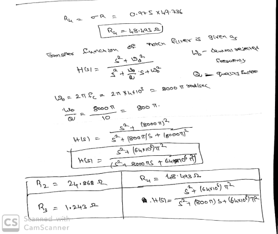
Part C Determine the resistance R2 in the filter Express your answer to three significant figures and include the appropriate units R2Value Units Submit Request Answer Part D Determine the resistance R3 in the filter Express your answer to three significant figures and include the appropriate units HA RValue Units Submit Request Answer Part E Determine the resistance R4 in the filter Express your answer to three significant figures and include the appropriate units R4-Value Units Submit Request Answer
▼ Part F What is the scaled transfer function of the filter? Express your answer in terms of s and T. vec H(s)- Submit Request Answer
Homework Answers


Add Answer to:
R1 = 49.7 Ohms, C1 = 1.60 uF Using the circuit shown in (Figure 1), design a narrow band bandreject filter having a center frequency of 4 kHz and a quality factor of 10. Base the design on igure 1 of...
Scale the bandpass filter in (Figure 1) so that the center frequency is 180 kHz and...
 Scale the bandpass filter in (Figure 1) so that the center frequency is 180 kHz and the quality factor is 8, using a 2.5 nF capacitor. Figure < 1 of 1 > 8k 310 mH 10 nF Part A Determine the value of the resistor of the scaled filter Express your answer to three significant figures and include the appropriate units. R = Value Units Submit Request Answer Part B Determine the value of the inductor of the scaled filter...
Part B Using C = 26 nF capacitors, design an active broadband first-order bandreject filter with...
 Part B Using C = 26 nF capacitors, design an active broadband first-order bandreject filter with a lower cutoff frequency of 400 Hz, an upper cutoff frequency of 4000 Hz, and a passband gain of 0 dB. Determine value of resistance in the high-pass filter RH. Express your answer to three significant figures and include the appropriate units. RH = Value Units Submit Request Answer Part C Determine value of resistance in the low-pass filter RL Express your answer to...
Homework #2 Problem 14.38 PSpice Multisim Part A Consider the bandreject filter shown in (Figure 1)....
 Homework #2 Problem 14.38 PSpice Multisim Part A Consider the bandreject filter shown in (Figure 1). Suppose that R-4 k2,L-3.5 mH, C-62.5 nF Calculate the center frequency wo. Express your answer using three significant figures vec krad/s Figure 1 of 1 Submit Request Answen Part B Calculate the center frequency f, in kilohertz. Express your answer using three significant figures vec kHz Problem 14.38 PSpice Multisim Part C Consider the bandreject filter shown in (Figure 1). Suppose that R-4 k2,L-3.5...
Find Power at R1, R2, and R3 Consider the circuit shown in (Figure 1). The source...
 Find Power at R1, R2, and
R3
Consider the circuit shown in (Figure 1). The source voltage viis 45 V. Resistance R1, R2 and R3 are 5 12,115 1 and 2512, respectively. The source current I is 20 mA. Find PR Express your answer to three significant figures and include the appropriate units. Ao aj ? Value Units PR = Submit Request Answer Part E Figure < 1 of 1 Find PR Express your answer to three significant figures and...
Find Power at R1, R2, and
R3
Consider the circuit shown in (Figure 1). The source voltage viis 45 V. Resistance R1, R2 and R3 are 5 12,115 1 and 2512, respectively. The source current I is 20 mA. Find PR Express your answer to three significant figures and include the appropriate units. Ao aj ? Value Units PR = Submit Request Answer Part E Figure < 1 of 1 Find PR Express your answer to three significant figures and...
Problem 4.7 Consider the circuit shown in (Figure 1). The source voltage v1 is 40 V....
 Problem 4.7 Consider the circuit shown in (Figure 1). The source voltage v1 is 40 V. Resistance R1, R2 and R3 are 5 ,120 and 15 , respectively. The source current I is 25 mA Part A Find the power developed by the current source I in the circuit. Express your answer to three significant figures and include the appropriate units. НА Value Units Рi 3 Request Answer Submit Part B Figure 1 of 1 Find the power developed by...
Design a bandpass filter, using a cascade connection, to give a center frequency of 600 Hz,...
 Design a bandpass filter, using a cascade connection, to give a center frequency of 600 Hz, a bandwidth of 2 kHz, and a passband gain of 4. Use 250 nF capacitors. Part A Specify fal Express your answer to three significant figures and include the appropriate units. Part B Specify f2. Express your answer to three significant figures and include the appropriate units. Part C Specify RL Express your answer to three significant figures and include the appropriate units. Part...
Consider the frame shown in (Figure 1). Assume A and B are pins and the joint...
 Consider the frame shown in (Figure 1). Assume A and B are pins and the joint at C is fixed connected. El is constant Part A Determine the x component of reaction at A. Express your answer to three significant figures and include the appropriate units. HA ? Value Units Submit Request Answer Part B Determine the y component of reaction at A. Express your answer to three significant figures and include the appropriate units. igure 1 of 1 НА...
Problem 15 15 of 21 > A Review Constants Using 2.7 K resistors and ideal op...
 Problem 15 15 of 21 > A Review Constants Using 2.7 K resistors and ideal op amps, design a circuit that will implement the low-pass Butterworth filter having a cutoll frequency of 600 Hz and the gain of no more than-32 dB at 2500 Hz. The gain in the passband is one Part A Determine the order of the low-pass Butterworth filter with given filter specifications. Express your answer as an integer. IVO AX t ? 11 = Submit Request...
Consider the frame shown in (Figure 1). EI is constant. Part A Determine the y component...
 Consider the frame shown in (Figure 1). EI is constant. Part A Determine the y component of reaction at A. Express your answer to three significant figures and include the appropriate units. -0% Ti A ? Ay = Value Units Submit Request Answer Part B Determine the component of reaction at C. Express your answer to three significant figures and include the appropriate units. igure 1 of 1 НА ? 6 m 18 kN/m C = Value Units B Submit...
 Scale the bandpass filter in (Figure 1) so that the center frequency is 180 kHz and the quality factor is 8, using a 2.5 nF capacitor. Figure < 1 of 1 > 8k 310 mH 10 nF Part A Determine the value of the resistor of the scaled filter Express your answer to three significant figures and include the appropriate units. R = Value Units Submit Request Answer Part B Determine the value of the inductor of the scaled filter...
 Part B Using C = 26 nF capacitors, design an active broadband first-order bandreject filter with a lower cutoff frequency of 400 Hz, an upper cutoff frequency of 4000 Hz, and a passband gain of 0 dB. Determine value of resistance in the high-pass filter RH. Express your answer to three significant figures and include the appropriate units. RH = Value Units Submit Request Answer Part C Determine value of resistance in the low-pass filter RL Express your answer to...
 Homework #2 Problem 14.38 PSpice Multisim Part A Consider the bandreject filter shown in (Figure 1). Suppose that R-4 k2,L-3.5 mH, C-62.5 nF Calculate the center frequency wo. Express your answer using three significant figures vec krad/s Figure 1 of 1 Submit Request Answen Part B Calculate the center frequency f, in kilohertz. Express your answer using three significant figures vec kHz Problem 14.38 PSpice Multisim Part C Consider the bandreject filter shown in (Figure 1). Suppose that R-4 k2,L-3.5...
 Find Power at R1, R2, and
R3
Consider the circuit shown in (Figure 1). The source voltage viis 45 V. Resistance R1, R2 and R3 are 5 12,115 1 and 2512, respectively. The source current I is 20 mA. Find PR Express your answer to three significant figures and include the appropriate units. Ao aj ? Value Units PR = Submit Request Answer Part E Figure < 1 of 1 Find PR Express your answer to three significant figures and...
Find Power at R1, R2, and
R3
Consider the circuit shown in (Figure 1). The source voltage viis 45 V. Resistance R1, R2 and R3 are 5 12,115 1 and 2512, respectively. The source current I is 20 mA. Find PR Express your answer to three significant figures and include the appropriate units. Ao aj ? Value Units PR = Submit Request Answer Part E Figure < 1 of 1 Find PR Express your answer to three significant figures and...
 Problem 4.7 Consider the circuit shown in (Figure 1). The source voltage v1 is 40 V. Resistance R1, R2 and R3 are 5 ,120 and 15 , respectively. The source current I is 25 mA Part A Find the power developed by the current source I in the circuit. Express your answer to three significant figures and include the appropriate units. НА Value Units Рi 3 Request Answer Submit Part B Figure 1 of 1 Find the power developed by...
 Design a bandpass filter, using a cascade connection, to give a center frequency of 600 Hz, a bandwidth of 2 kHz, and a passband gain of 4. Use 250 nF capacitors. Part A Specify fal Express your answer to three significant figures and include the appropriate units. Part B Specify f2. Express your answer to three significant figures and include the appropriate units. Part C Specify RL Express your answer to three significant figures and include the appropriate units. Part...
 Consider the frame shown in (Figure 1). Assume A and B are pins and the joint at C is fixed connected. El is constant Part A Determine the x component of reaction at A. Express your answer to three significant figures and include the appropriate units. HA ? Value Units Submit Request Answer Part B Determine the y component of reaction at A. Express your answer to three significant figures and include the appropriate units. igure 1 of 1 НА...
 Problem 15 15 of 21 > A Review Constants Using 2.7 K resistors and ideal op amps, design a circuit that will implement the low-pass Butterworth filter having a cutoll frequency of 600 Hz and the gain of no more than-32 dB at 2500 Hz. The gain in the passband is one Part A Determine the order of the low-pass Butterworth filter with given filter specifications. Express your answer as an integer. IVO AX t ? 11 = Submit Request...
 Consider the frame shown in (Figure 1). EI is constant. Part A Determine the y component of reaction at A. Express your answer to three significant figures and include the appropriate units. -0% Ti A ? Ay = Value Units Submit Request Answer Part B Determine the component of reaction at C. Express your answer to three significant figures and include the appropriate units. igure 1 of 1 НА ? 6 m 18 kN/m C = Value Units B Submit...
 Consider the frame shown in (Figure 1). EI is constant. Part A Determine the y component of reaction at A. Express your answer to three significant figures and include the appropriate units. -0% Ti A ? Ay = Value Units Submit Request Answer Part B Determine the component of reaction at C. Express your answer to three significant figures and include the appropriate units. igure 1 of 1 НА ? 6 m 18 kN/m C = Value Units B Submit...
Most questions answered within 3 hours.
-
For a 2-Level design, with 8 factors, a recommended screening
design model is:
a. Taguchi L12...
asked 35 minutes ago -
1. Define a function in python that returns the sum of the
following 4 lists. Remember...
asked 26 minutes ago -
Elspeth, associate research specialist for a marketing research
firm in a large Midwestern city, had just...
asked 26 minutes ago -
If domestic savings are insufficient to finance domestic private
investment and exports are greater than imports,...
asked 41 minutes ago -
Q.4.
Use the format in Exhibit 9-1 to compute the ending LIFO
inventory and cost of...
asked 47 minutes ago -
Discuss the different receiving and dispatch equipment required
for uploading and loading different types of material...
asked 51 minutes ago -
Which of the following is true for simultaneous testing?
a. Net specificity is greater than the...
asked 55 minutes ago -
Discuss the importance of homologous recombination and
transposition in natural horizontal gene transfer and evolution. Be...
asked 59 minutes ago -
Brittle material has the properties Sut = 30 kpsi and Suc = 90
kpsi. Using the...
asked 58 minutes ago -
*
write about Plastic recycling statistics ( Plastic recycling rate )
last two years , i...
asked 57 minutes ago -
The activation energy for a given reaction is 50.3 kJ/mol. If
the rate constant for the...
asked 1 hour ago -
An entomologist discovers a dung beetle rolling a ball of dung
along the ground, and decides...
asked 3 hours ago