
Homework Answers
Add Answer to:
What stresses would you need to calculate in order to develop the 2D state of stress for point B on the cross section of the pipe assembly 400 mm al 200 mm 1500 N 1000 N 20 mm Section a-a a. Normal s...
Learning Goal: To calculate the normal and shear stresses at a point on the cross section...
 Learning Goal: To calculate the normal and shear stresses at a point on the cross section of a column. The state of stress at a point is a description of the normal and shear stresses at that point. The normal stresses are generally due to both internal normal force and internal bending moment. The net result can be obtained using the principle of superposition as long as the deflections remain small and the response is elastic. Figure < 1 of...
For the pipe assembly shown below, a) determine the internal loads in section a-a b) identify...
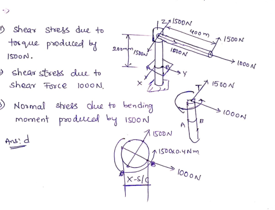
 For the pipe assembly shown below, a) determine the internal loads in section a-a b) identify the types of loads (axial, bending, torsion, etc...) c) determine the state of stress at point A d) show the results in a differential volumetric element at A. 400 mm 200 mm 1500 N 20 mm 1000 N Section a-a
A column with a wide-flange section has a flange width b = 400 mm , height...
 A column with a wide-flange section has a flange width
b = 400 mm , height h = 400 mm , web thickness
tw = 13 mm , and flange thickness
tf = 21 mm (Figure 1). Calculate the stresses at
a point 65 mm above the neutral axis if the section supports a
tensile normal force N = 3 kN at the centroid, shear force
V = 7.4 kN , and bending moment M = 4 kN⋅m as
shown...
A column with a wide-flange section has a flange width
b = 400 mm , height h = 400 mm , web thickness
tw = 13 mm , and flange thickness
tf = 21 mm (Figure 1). Calculate the stresses at
a point 65 mm above the neutral axis if the section supports a
tensile normal force N = 3 kN at the centroid, shear force
V = 7.4 kN , and bending moment M = 4 kN⋅m as
shown...
Determine the state of stress at point A on the cross section of the pipe assembly...
 Determine the state of stress at point A on the cross section of the pipe assembly at section a-a. Take Fi = 1480 N. F2 = 1090 N (Figure 1) Express your answer to three significant figures and include the appropriate units. Enter negative value in the case of compression and positive in the case of tension. НА ? Figure < 1 of 1 Value Units Submit Request Answer 400 mm Part B 200 mm Fi Find (Tay) Express your...
1. The part shown consists of a bent rod with a solid circular cross section of...
 1. The part shown consists of a bent rod with a solid circular cross section of diameter 20 mm. Consider the cross- section on a cut at both a-a, and b-b. 400 mm A] For each cut, label the shear force, bending moments, and torsion moments. Then determine the critical point with the highest normal stress at each cross- section. No stress calculations are required. /100 mm 1 BJ Determine the point of highest normal stress for the bent rod...
7) Given the state of stress at point A on the circular cross section a-a of...
 7) Given the state of stress at point A on the circular cross section a-a of the handle assembly is oz 47.11 MPa, ryz = 48.81 MPa. Show the results on the volume element shown. 800 N 400 mm 200 mm 1500 N 20 mm1000 N Section a-a
10 mm 10 mm 300 N/m 50 mm 10 mm Problem 2. Consider the beam above with the cross-section shown. ...
 please solve 1-5 and show all steps and equations used
10 mm 10 mm 300 N/m 50 mm 10 mm Problem 2. Consider the beam above with the cross-section shown. The number (300N/m) indicates the value of the load distribution at its peak. (5 pts.) Find the reactions (15 pts.) Draw the shear and moment diagrams using the graphical method. Ensure you state values of the diagrams, and type of function for lincar or higher-order segments. You can indicate all...
please solve 1-5 and show all steps and equations used
10 mm 10 mm 300 N/m 50 mm 10 mm Problem 2. Consider the beam above with the cross-section shown. The number (300N/m) indicates the value of the load distribution at its peak. (5 pts.) Find the reactions (15 pts.) Draw the shear and moment diagrams using the graphical method. Ensure you state values of the diagrams, and type of function for lincar or higher-order segments. You can indicate all...
1) For the loading of the beam shown below, determine the maximum normal and shear stress...
 1) For the loading of the beam shown below, determine the maximum normal and shear stress at the wall if Kt for bending is 2.7 and K, for torsion is 2.3 If we use a steel with an Sy 600 MPa, what is the "safety factor" if we only consider the maximum normal stress? Notice the bending moment, start with a cross product to determine the moment at the wall. The vector R-[0.25,0,0.3] in meters 200 mm 25-mm-dia. round rod...
Problem 1: A shaft, with a diameter of 43 mm, is shown below. On the right-hand side at location ...
 Problem 1: A shaft, with a diameter of 43 mm, is shown below. On the right-hand side at location D a wheel has a force F of 4824N applied. The diameter of this wheel is 150 mm. The torque produced by F is transmitted through the entire shaft to location A where the torque is reacted. There are no other constraints at location A. Bearings, are located at B and C, and provide radial constraint. The bearing at B also...
PROBLEM 2: 40% A 6 kN force is exerted on the frame which has the T cross sectio analyze the states of stress at a section taken at 800 mm from the point of n shown below. It is required to 1. Fo...
 PROBLEM 2: 40% A 6 kN force is exerted on the frame which has the T cross sectio analyze the states of stress at a section taken at 800 mm from the point of n shown below. It is required to 1. For the given T cross section, find the centroid and the area moment of inertia I,. 2. Draw the free body diagram of the free end of the frame and determine the interna loadings at the centroid of...
 Learning Goal: To calculate the normal and shear stresses at a point on the cross section of a column. The state of stress at a point is a description of the normal and shear stresses at that point. The normal stresses are generally due to both internal normal force and internal bending moment. The net result can be obtained using the principle of superposition as long as the deflections remain small and the response is elastic. Figure < 1 of...
 For the pipe assembly shown below, a) determine the internal loads in section a-a b) identify the types of loads (axial, bending, torsion, etc...) c) determine the state of stress at point A d) show the results in a differential volumetric element at A. 400 mm 200 mm 1500 N 20 mm 1000 N Section a-a
 A column with a wide-flange section has a flange width
b = 400 mm , height h = 400 mm , web thickness
tw = 13 mm , and flange thickness
tf = 21 mm (Figure 1). Calculate the stresses at
a point 65 mm above the neutral axis if the section supports a
tensile normal force N = 3 kN at the centroid, shear force
V = 7.4 kN , and bending moment M = 4 kN⋅m as
shown...
A column with a wide-flange section has a flange width
b = 400 mm , height h = 400 mm , web thickness
tw = 13 mm , and flange thickness
tf = 21 mm (Figure 1). Calculate the stresses at
a point 65 mm above the neutral axis if the section supports a
tensile normal force N = 3 kN at the centroid, shear force
V = 7.4 kN , and bending moment M = 4 kN⋅m as
shown...
 Determine the state of stress at point A on the cross section of the pipe assembly at section a-a. Take Fi = 1480 N. F2 = 1090 N (Figure 1) Express your answer to three significant figures and include the appropriate units. Enter negative value in the case of compression and positive in the case of tension. НА ? Figure < 1 of 1 Value Units Submit Request Answer 400 mm Part B 200 mm Fi Find (Tay) Express your...
 1. The part shown consists of a bent rod with a solid circular cross section of diameter 20 mm. Consider the cross- section on a cut at both a-a, and b-b. 400 mm A] For each cut, label the shear force, bending moments, and torsion moments. Then determine the critical point with the highest normal stress at each cross- section. No stress calculations are required. /100 mm 1 BJ Determine the point of highest normal stress for the bent rod...
 7) Given the state of stress at point A on the circular cross section a-a of the handle assembly is oz 47.11 MPa, ryz = 48.81 MPa. Show the results on the volume element shown. 800 N 400 mm 200 mm 1500 N 20 mm1000 N Section a-a
 please solve 1-5 and show all steps and equations used
10 mm 10 mm 300 N/m 50 mm 10 mm Problem 2. Consider the beam above with the cross-section shown. The number (300N/m) indicates the value of the load distribution at its peak. (5 pts.) Find the reactions (15 pts.) Draw the shear and moment diagrams using the graphical method. Ensure you state values of the diagrams, and type of function for lincar or higher-order segments. You can indicate all...
please solve 1-5 and show all steps and equations used
10 mm 10 mm 300 N/m 50 mm 10 mm Problem 2. Consider the beam above with the cross-section shown. The number (300N/m) indicates the value of the load distribution at its peak. (5 pts.) Find the reactions (15 pts.) Draw the shear and moment diagrams using the graphical method. Ensure you state values of the diagrams, and type of function for lincar or higher-order segments. You can indicate all...
 1) For the loading of the beam shown below, determine the maximum normal and shear stress at the wall if Kt for bending is 2.7 and K, for torsion is 2.3 If we use a steel with an Sy 600 MPa, what is the "safety factor" if we only consider the maximum normal stress? Notice the bending moment, start with a cross product to determine the moment at the wall. The vector R-[0.25,0,0.3] in meters 200 mm 25-mm-dia. round rod...
 Problem 1: A shaft, with a diameter of 43 mm, is shown below. On the right-hand side at location D a wheel has a force F of 4824N applied. The diameter of this wheel is 150 mm. The torque produced by F is transmitted through the entire shaft to location A where the torque is reacted. There are no other constraints at location A. Bearings, are located at B and C, and provide radial constraint. The bearing at B also...
 PROBLEM 2: 40% A 6 kN force is exerted on the frame which has the T cross sectio analyze the states of stress at a section taken at 800 mm from the point of n shown below. It is required to 1. For the given T cross section, find the centroid and the area moment of inertia I,. 2. Draw the free body diagram of the free end of the frame and determine the interna loadings at the centroid of...
Most questions answered within 3 hours.
-
A circus performer stands on a platform and throws an apple from
a height of 44...
asked 8 minutes ago -
A project has an initial cost of $200,000 and uniform annual
benefits of $35,000. At the...
asked 12 minutes ago -
For a web site, computer program, or smartphone app of
your choice, write five user stories...
asked 20 minutes ago -
Decision Making Technology at UPS
Regardless of the specific decisions a manager makes, the
decision-making process...
asked 29 minutes ago -
Cadherins are transmembrane receptors that have 3
structural domains, each with distinct functions. Describe the
structure...
asked 51 minutes ago -
Oslo Company prepared the following contribution format income
statement based on a sales volume of 1,000...
asked 43 minutes ago -
Suppose you are a distance r from a magnetic dipole. Far from
the dipole, the magnetic...
asked 51 minutes ago -
The potential in a region of space due to a charge distribution
is given by the...
asked 48 minutes ago -
Extension of the shoulder joint is described as
a.
Movement of the humerus straight posteriorly from...
asked 55 minutes ago -
Suppose Nancy Ford buys a brand new Chevy Cruze in September
2019. The car comes up...
asked 57 minutes ago -
Each beaker in a series contains an identical sample of an
acetic acid/sodium acetate buffer. The...
asked 1 hour ago -
Plato and Aristotle comprise two basic, but different, elements
of the western intellectual tradition. Compare and...
asked 1 hour ago