A column with a wide-flange section has a flange width
b = 400 mm , height h = 400 mm , web thickness
tw = 13 mm , and flange thickness
tf = 21 mm (Figure 1). Calculate the stresses at
a point 65 mm above the neutral axis if the section supports a
tensile normal force N = 3 kN at the centroid, shear force
V = 7.4 kN , and bending moment M = 4 kN⋅m as
shown (Figure 2). 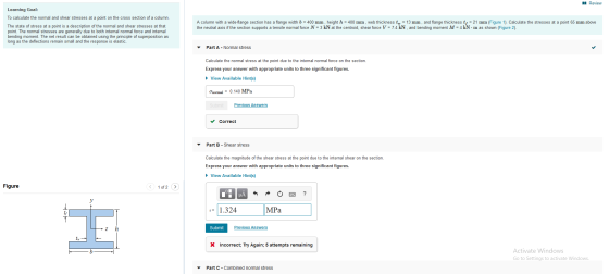

Homework Answers


Add Answer to:
A column with a wide-flange section has a flange width
b = 400 mm , height...
Learning Goal: To calculate the normal and shear stresses at a point on the cross section...
 Learning Goal: To calculate the normal and shear stresses at a point on the cross section of a column. The state of stress at a point is a description of the normal and shear stresses at that point. The normal stresses are generally due to both internal normal force and internal bending moment. The net result can be obtained using the principle of superposition as long as the deflections remain small and the response is elastic. Figure < 1 of...
will upvote thank you! please try and be as detailed as possible to further my understanding...
 will upvote thank you! please try and be as detailed as
possible to further my understanding
Learning Goal: To calculate the normal and shear stresses at a point on the cross section of a column. The state of stress at a point is a description of the normal and shear stresses at that point. The normal stresses are generally due to both internal normal force and internal bending moment. The net result can be obtained using the principle of superposition...
will upvote thank you! please try and be as detailed as
possible to further my understanding
Learning Goal: To calculate the normal and shear stresses at a point on the cross section of a column. The state of stress at a point is a description of the normal and shear stresses at that point. The normal stresses are generally due to both internal normal force and internal bending moment. The net result can be obtained using the principle of superposition...
Part B?? An l-beam has a flange width b-250 mm , height h = 250 mm...
 Part B??
An l-beam has a flange width b-250 mm , height h = 250 mm , web thickness tw-9 mm , and flange thickness tf = 14 mm . Use the following steps to calculate the shear flow at the point shown, where z = 80 mm Learning Goal: To calculate the shear flow at a point in the flange of an I-beam section subject to a shear force. A thin-walled structure is one where the wall thickness is...
Part B??
An l-beam has a flange width b-250 mm , height h = 250 mm , web thickness tw-9 mm , and flange thickness tf = 14 mm . Use the following steps to calculate the shear flow at the point shown, where z = 80 mm Learning Goal: To calculate the shear flow at a point in the flange of an I-beam section subject to a shear force. A thin-walled structure is one where the wall thickness is...
An I-beam has a flange width b = 200 mm , height h = 200 mm , web thickness tw = 8 mm , and flange thickness tf = 12 mm...
 An I-beam has a flange width b = 200 mm , height h = 200 mm ,
web thickness tw = 8 mm , and flange thickness
tf = 12 mm . Use the following steps to calculate the
shear stress at a point 65 mm above the neutral axis.
Part A - Moment of inertia
The shear formula includes the moment of inertia of the whole
cross section, I, about the neutral axis. Calculate the moment of
inertia.
Express...
An I-beam has a flange width b = 200 mm , height h = 200 mm ,
web thickness tw = 8 mm , and flange thickness
tf = 12 mm . Use the following steps to calculate the
shear stress at a point 65 mm above the neutral axis.
Part A - Moment of inertia
The shear formula includes the moment of inertia of the whole
cross section, I, about the neutral axis. Calculate the moment of
inertia.
Express...
What stresses would you need to calculate in order to develop the 2D state of stress for point B on the cross section of the pipe assembly 400 mm al 200 mm 1500 N 1000 N 20 mm Section a-a a. Normal s...
 What stresses would you need to calculate in order to develop the 2D state of stress for point B on the cross section of the pipe assembly 400 mm al 200 mm 1500 N 1000 N 20 mm Section a-a a. Normal stress due to normal force, normal stress due to bending moment b. Shear stress due to shear force, normal stress due to normal force, normal stress due to bending moment due to normal force, normal stress due to...
The beam shown (Figure 1) is supported by a pin at A and a cable at...
 The beam shown (Figure 1) is
supported by a pin at A and a cable at B. Two
loads P = 13 kN are applied straight down from the
centerline of the bottom face. Determine the state of stress at the
point shown (Figure 2) in a section 2 m from the wall. The
dimensions are w = 5.2 cm , h = 10.5 cm ,
L = 0.8 m , a = 1.5 cm , and b = 4...
The beam shown (Figure 1) is
supported by a pin at A and a cable at B. Two
loads P = 13 kN are applied straight down from the
centerline of the bottom face. Determine the state of stress at the
point shown (Figure 2) in a section 2 m from the wall. The
dimensions are w = 5.2 cm , h = 10.5 cm ,
L = 0.8 m , a = 1.5 cm , and b = 4...
The internal shear force at a certain section of a steel beam is V=185 kN. The...
 The internal shear force at a certain section of a steel beam is
V=185 kN. The beam cross section shown in the figure has dimensions
of tf=17 mm, bf=300 mm, d=394 mm, and tw=10 mm. Determine:
(a) the shear stress at point A, which is located at
yA=71 mm below the centroid of the wide-flange shape.
(b) the maximum horizontal shear stress in the wide-flange
shape.
The internal shear force at a certain section of a steel beam is V=...
The internal shear force at a certain section of a steel beam is
V=185 kN. The beam cross section shown in the figure has dimensions
of tf=17 mm, bf=300 mm, d=394 mm, and tw=10 mm. Determine:
(a) the shear stress at point A, which is located at
yA=71 mm below the centroid of the wide-flange shape.
(b) the maximum horizontal shear stress in the wide-flange
shape.
The internal shear force at a certain section of a steel beam is V=...
(a) If the wide-flange beam shown in Figure Q4a is subjected to a shear of V = 23 kN
 (a) If the wide-flange beam shown in Figure Q4a is subjected to a shear of V = 23 kN i. Calculate the moment of inertia of the cross section about the neutral axis.ii. Determine the shear stress on the web at A.(b) The state of stress at a point is shown on the element in Figure Q4b. Determine graphically using Mohr's circle i. The principal stresses. ii. The orientation of the principal planes.iii. The maximum in-plane shear stress and average normal stress at...
The internal shear force at a certain section of a steel beam is V = 205...
 The internal shear force at a certain section of a steel beam is V = 205 KN. The beam cross section shown in the figure has dimensions of ty = 21 mm, b = 285 mm, d = 410 mm, and = 14 mm. Determine: (a) the shear stress at point A, which is located at y = 75 mm below the centroid of the wide-flange shape. (b) the maximum horizontal shear stress in the wide-flange shape. YA by Below,...
The beam shown (Figure 1) is supported by a pin at A and a cable at...
 The beam shown (Figure 1) is supported by a pin at A
and a cable at B. Two loads P = 13 kN are applied
straight down from the centerline of the bottom face. Determine the
state of stress at the point shown (Figure 2) in a section 2 m from
the wall. The dimensions are w = 5.2 cm , h =
10.5 cm , L = 0.8 m , a = 1.5 cm , and b
= 4...
The beam shown (Figure 1) is supported by a pin at A
and a cable at B. Two loads P = 13 kN are applied
straight down from the centerline of the bottom face. Determine the
state of stress at the point shown (Figure 2) in a section 2 m from
the wall. The dimensions are w = 5.2 cm , h =
10.5 cm , L = 0.8 m , a = 1.5 cm , and b
= 4...
 Learning Goal: To calculate the normal and shear stresses at a point on the cross section of a column. The state of stress at a point is a description of the normal and shear stresses at that point. The normal stresses are generally due to both internal normal force and internal bending moment. The net result can be obtained using the principle of superposition as long as the deflections remain small and the response is elastic. Figure < 1 of...
 will upvote thank you! please try and be as detailed as
possible to further my understanding
Learning Goal: To calculate the normal and shear stresses at a point on the cross section of a column. The state of stress at a point is a description of the normal and shear stresses at that point. The normal stresses are generally due to both internal normal force and internal bending moment. The net result can be obtained using the principle of superposition...
will upvote thank you! please try and be as detailed as
possible to further my understanding
Learning Goal: To calculate the normal and shear stresses at a point on the cross section of a column. The state of stress at a point is a description of the normal and shear stresses at that point. The normal stresses are generally due to both internal normal force and internal bending moment. The net result can be obtained using the principle of superposition...
 Part B??
An l-beam has a flange width b-250 mm , height h = 250 mm , web thickness tw-9 mm , and flange thickness tf = 14 mm . Use the following steps to calculate the shear flow at the point shown, where z = 80 mm Learning Goal: To calculate the shear flow at a point in the flange of an I-beam section subject to a shear force. A thin-walled structure is one where the wall thickness is...
Part B??
An l-beam has a flange width b-250 mm , height h = 250 mm , web thickness tw-9 mm , and flange thickness tf = 14 mm . Use the following steps to calculate the shear flow at the point shown, where z = 80 mm Learning Goal: To calculate the shear flow at a point in the flange of an I-beam section subject to a shear force. A thin-walled structure is one where the wall thickness is...
 An I-beam has a flange width b = 200 mm , height h = 200 mm ,
web thickness tw = 8 mm , and flange thickness
tf = 12 mm . Use the following steps to calculate the
shear stress at a point 65 mm above the neutral axis.
Part A - Moment of inertia
The shear formula includes the moment of inertia of the whole
cross section, I, about the neutral axis. Calculate the moment of
inertia.
Express...
An I-beam has a flange width b = 200 mm , height h = 200 mm ,
web thickness tw = 8 mm , and flange thickness
tf = 12 mm . Use the following steps to calculate the
shear stress at a point 65 mm above the neutral axis.
Part A - Moment of inertia
The shear formula includes the moment of inertia of the whole
cross section, I, about the neutral axis. Calculate the moment of
inertia.
Express...
 What stresses would you need to calculate in order to develop the 2D state of stress for point B on the cross section of the pipe assembly 400 mm al 200 mm 1500 N 1000 N 20 mm Section a-a a. Normal stress due to normal force, normal stress due to bending moment b. Shear stress due to shear force, normal stress due to normal force, normal stress due to bending moment due to normal force, normal stress due to...
 The beam shown (Figure 1) is
supported by a pin at A and a cable at B. Two
loads P = 13 kN are applied straight down from the
centerline of the bottom face. Determine the state of stress at the
point shown (Figure 2) in a section 2 m from the wall. The
dimensions are w = 5.2 cm , h = 10.5 cm ,
L = 0.8 m , a = 1.5 cm , and b = 4...
The beam shown (Figure 1) is
supported by a pin at A and a cable at B. Two
loads P = 13 kN are applied straight down from the
centerline of the bottom face. Determine the state of stress at the
point shown (Figure 2) in a section 2 m from the wall. The
dimensions are w = 5.2 cm , h = 10.5 cm ,
L = 0.8 m , a = 1.5 cm , and b = 4...
 The internal shear force at a certain section of a steel beam is
V=185 kN. The beam cross section shown in the figure has dimensions
of tf=17 mm, bf=300 mm, d=394 mm, and tw=10 mm. Determine:
(a) the shear stress at point A, which is located at
yA=71 mm below the centroid of the wide-flange shape.
(b) the maximum horizontal shear stress in the wide-flange
shape.
The internal shear force at a certain section of a steel beam is V=...
The internal shear force at a certain section of a steel beam is
V=185 kN. The beam cross section shown in the figure has dimensions
of tf=17 mm, bf=300 mm, d=394 mm, and tw=10 mm. Determine:
(a) the shear stress at point A, which is located at
yA=71 mm below the centroid of the wide-flange shape.
(b) the maximum horizontal shear stress in the wide-flange
shape.
The internal shear force at a certain section of a steel beam is V=...
 The internal shear force at a certain section of a steel beam is V = 205 KN. The beam cross section shown in the figure has dimensions of ty = 21 mm, b = 285 mm, d = 410 mm, and = 14 mm. Determine: (a) the shear stress at point A, which is located at y = 75 mm below the centroid of the wide-flange shape. (b) the maximum horizontal shear stress in the wide-flange shape. YA by Below,...
 The beam shown (Figure 1) is supported by a pin at A
and a cable at B. Two loads P = 13 kN are applied
straight down from the centerline of the bottom face. Determine the
state of stress at the point shown (Figure 2) in a section 2 m from
the wall. The dimensions are w = 5.2 cm , h =
10.5 cm , L = 0.8 m , a = 1.5 cm , and b
= 4...
The beam shown (Figure 1) is supported by a pin at A
and a cable at B. Two loads P = 13 kN are applied
straight down from the centerline of the bottom face. Determine the
state of stress at the point shown (Figure 2) in a section 2 m from
the wall. The dimensions are w = 5.2 cm , h =
10.5 cm , L = 0.8 m , a = 1.5 cm , and b
= 4...
Most questions answered within 3 hours.
-
Find a map online of major or minor tectonic plates, and choose
one of interest to...
asked 12 minutes ago -
5. Explain why direct antigen activation of CTLs and B cells is
more important than APC-initiated...
asked 18 minutes ago -
Seaborgium (Z= 106) can be synthesized by the bombardment of
249Cf with 16O. If four (4)...
asked 25 minutes ago -
acorn holdings, a Uk company is entering into a long term
agreement with Ahmed Habib Textiles,...
asked 23 minutes ago -
A methodology to help create stability in a process is
Wh
Question 11 options:
Daily meetings...
asked 24 minutes ago -
Km = {(Vmax([S]))/(V)} – [S]
• Vmax = 100 (units)
• At [S] = 20 M...
asked 25 minutes ago -
Suggest a way to distinguish Citrobacter freundii from
Escherichia coli and from Proteus species.
asked 40 minutes ago -
Compute the IRR static for Project E. The appropriate
cost of capital is 9 percent. 0...
asked 1 hour ago -
The distribution of a test's scores for college-bound male
seniors has a mean of 1523 and...
asked 1 hour ago -
Valiant Industries has 30 million shares of stock outstanding at
a price of $25.44 per share....
asked 1 hour ago -
I need help with my javascript project, I've started on it but I
can't seem to...
asked 3 hours ago -
Identification of unknown Bacteria by sequencing
rDNA
Having a little trouble understanding the PCR process. This...
asked 3 hours ago