

Homework Answers


Add Answer to:
will upvote thank you! please try and be as detailed as
possible to further my understanding...
A column with a wide-flange section has a flange width b = 400 mm , height...
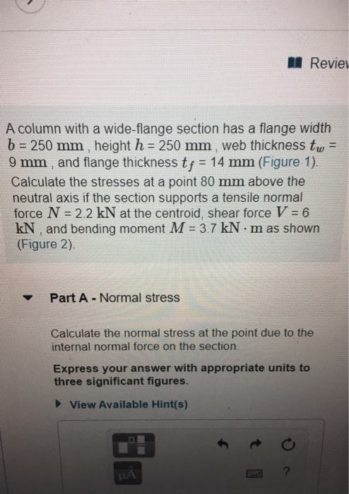
 A column with a wide-flange section has a flange width
b = 400 mm , height h = 400 mm , web thickness
tw = 13 mm , and flange thickness
tf = 21 mm (Figure 1). Calculate the stresses at
a point 65 mm above the neutral axis if the section supports a
tensile normal force N = 3 kN at the centroid, shear force
V = 7.4 kN , and bending moment M = 4 kN⋅m as
shown...
A column with a wide-flange section has a flange width
b = 400 mm , height h = 400 mm , web thickness
tw = 13 mm , and flange thickness
tf = 21 mm (Figure 1). Calculate the stresses at
a point 65 mm above the neutral axis if the section supports a
tensile normal force N = 3 kN at the centroid, shear force
V = 7.4 kN , and bending moment M = 4 kN⋅m as
shown...
Learning Goal: To calculate the normal and shear stresses at a point on the cross section...
 Learning Goal: To calculate the normal and shear stresses at a point on the cross section of a column. The state of stress at a point is a description of the normal and shear stresses at that point. The normal stresses are generally due to both internal normal force and internal bending moment. The net result can be obtained using the principle of superposition as long as the deflections remain small and the response is elastic. Figure < 1 of...
Learning Goal: The beam shown (Figure 1) is supported by a pin at A and a...
 Learning Goal: The beam shown (Figure 1) is supported by a pin at A and a cable at B. Two loads P = 18 kN are applied straight down from the centerline of the bottom face. Determine the state of stress at the point shown (Figure 2) in a section 2 m from the wall. The dimensions are w = 5.4 cm , h = 12 cm, L = 0.8 m, a = 1.5 cm , and b = 4...
Part B?? An l-beam has a flange width b-250 mm , height h = 250 mm...
 Part B??
An l-beam has a flange width b-250 mm , height h = 250 mm , web thickness tw-9 mm , and flange thickness tf = 14 mm . Use the following steps to calculate the shear flow at the point shown, where z = 80 mm Learning Goal: To calculate the shear flow at a point in the flange of an I-beam section subject to a shear force. A thin-walled structure is one where the wall thickness is...
Part B??
An l-beam has a flange width b-250 mm , height h = 250 mm , web thickness tw-9 mm , and flange thickness tf = 14 mm . Use the following steps to calculate the shear flow at the point shown, where z = 80 mm Learning Goal: To calculate the shear flow at a point in the flange of an I-beam section subject to a shear force. A thin-walled structure is one where the wall thickness is...
Learning Goal: To determine the state of stress in a solid rod using the principle of...
 Learning Goal: To determine the state of stress in a solid rod using the principle of superposition. A solid rod has a diameter of e = 55 mm and is subjected to the loading shown. Let a = 190 mm, b = 220 mm , c = 350 mm, d = 240 mm , and P = 4.0 kN. Take point A to be at the top of the circular cross-section. (Figure 1) Figure < 1 of 2 b В...
Part A - Moment about the x axis at A Learning Goal: To determine the state...
 Part A - Moment about the x axis at A Learning Goal: To determine the state of stress in a solid rod using the principle of superposition. A solid rod has a diameter of e = 60 mm and is subjected to the loading shown. Let a = 200 mm, b = 220 mm c = 340 mm, d = 230 mm, and P = 4.0 kN. Take point A to be at the top of the circular cross-section. (Figure...
An I-beam has a flange width b = 200 mm , height h = 200 mm , web thickness tw = 8 mm , and flange thickness tf = 12 mm...
 An I-beam has a flange width b = 200 mm , height h = 200 mm ,
web thickness tw = 8 mm , and flange thickness
tf = 12 mm . Use the following steps to calculate the
shear stress at a point 65 mm above the neutral axis.
Part A - Moment of inertia
The shear formula includes the moment of inertia of the whole
cross section, I, about the neutral axis. Calculate the moment of
inertia.
Express...
An I-beam has a flange width b = 200 mm , height h = 200 mm ,
web thickness tw = 8 mm , and flange thickness
tf = 12 mm . Use the following steps to calculate the
shear stress at a point 65 mm above the neutral axis.
Part A - Moment of inertia
The shear formula includes the moment of inertia of the whole
cross section, I, about the neutral axis. Calculate the moment of
inertia.
Express...
The beam shown (Figure 1) is supported by a pin at A and a cable at...
 The beam shown (Figure 1) is
supported by a pin at A and a cable at B. Two
loads P = 13 kN are applied straight down from the
centerline of the bottom face. Determine the state of stress at the
point shown (Figure 2) in a section 2 m from the wall. The
dimensions are w = 5.2 cm , h = 10.5 cm ,
L = 0.8 m , a = 1.5 cm , and b = 4...
The beam shown (Figure 1) is
supported by a pin at A and a cable at B. Two
loads P = 13 kN are applied straight down from the
centerline of the bottom face. Determine the state of stress at the
point shown (Figure 2) in a section 2 m from the wall. The
dimensions are w = 5.2 cm , h = 10.5 cm ,
L = 0.8 m , a = 1.5 cm , and b = 4...
The beam shown (Figure 1) is supported by a pin at A and a cable at...
 The beam shown (Figure 1) is supported by a pin at A
and a cable at B. Two loads P = 13 kN are applied
straight down from the centerline of the bottom face. Determine the
state of stress at the point shown (Figure 2) in a section 2 m from
the wall. The dimensions are w = 5.2 cm , h =
10.5 cm , L = 0.8 m , a = 1.5 cm , and b
= 4...
The beam shown (Figure 1) is supported by a pin at A
and a cable at B. Two loads P = 13 kN are applied
straight down from the centerline of the bottom face. Determine the
state of stress at the point shown (Figure 2) in a section 2 m from
the wall. The dimensions are w = 5.2 cm , h =
10.5 cm , L = 0.8 m , a = 1.5 cm , and b
= 4...
The beam shown (Figure 1) is supported by a pin at A and a cable at...
 The beam shown (Figure 1) is supported by a pin at A and a cable at
B. Two loads P = 13 kN are applied straight down
from the centerline of the bottom face. Determine the state of
stress at the point shown (Figure 2) in a section 2 m from the
wall. The dimensions are w = 5.2 cm , h = 10.5 cm
, L = 0.8 m , a = 1.5 cm , and b = 4...
The beam shown (Figure 1) is supported by a pin at A and a cable at
B. Two loads P = 13 kN are applied straight down
from the centerline of the bottom face. Determine the state of
stress at the point shown (Figure 2) in a section 2 m from the
wall. The dimensions are w = 5.2 cm , h = 10.5 cm
, L = 0.8 m , a = 1.5 cm , and b = 4...
 A column with a wide-flange section has a flange width
b = 400 mm , height h = 400 mm , web thickness
tw = 13 mm , and flange thickness
tf = 21 mm (Figure 1). Calculate the stresses at
a point 65 mm above the neutral axis if the section supports a
tensile normal force N = 3 kN at the centroid, shear force
V = 7.4 kN , and bending moment M = 4 kN⋅m as
shown...
A column with a wide-flange section has a flange width
b = 400 mm , height h = 400 mm , web thickness
tw = 13 mm , and flange thickness
tf = 21 mm (Figure 1). Calculate the stresses at
a point 65 mm above the neutral axis if the section supports a
tensile normal force N = 3 kN at the centroid, shear force
V = 7.4 kN , and bending moment M = 4 kN⋅m as
shown...
 Learning Goal: To calculate the normal and shear stresses at a point on the cross section of a column. The state of stress at a point is a description of the normal and shear stresses at that point. The normal stresses are generally due to both internal normal force and internal bending moment. The net result can be obtained using the principle of superposition as long as the deflections remain small and the response is elastic. Figure < 1 of...
 Learning Goal: The beam shown (Figure 1) is supported by a pin at A and a cable at B. Two loads P = 18 kN are applied straight down from the centerline of the bottom face. Determine the state of stress at the point shown (Figure 2) in a section 2 m from the wall. The dimensions are w = 5.4 cm , h = 12 cm, L = 0.8 m, a = 1.5 cm , and b = 4...
 Part B??
An l-beam has a flange width b-250 mm , height h = 250 mm , web thickness tw-9 mm , and flange thickness tf = 14 mm . Use the following steps to calculate the shear flow at the point shown, where z = 80 mm Learning Goal: To calculate the shear flow at a point in the flange of an I-beam section subject to a shear force. A thin-walled structure is one where the wall thickness is...
Part B??
An l-beam has a flange width b-250 mm , height h = 250 mm , web thickness tw-9 mm , and flange thickness tf = 14 mm . Use the following steps to calculate the shear flow at the point shown, where z = 80 mm Learning Goal: To calculate the shear flow at a point in the flange of an I-beam section subject to a shear force. A thin-walled structure is one where the wall thickness is...
 Learning Goal: To determine the state of stress in a solid rod using the principle of superposition. A solid rod has a diameter of e = 55 mm and is subjected to the loading shown. Let a = 190 mm, b = 220 mm , c = 350 mm, d = 240 mm , and P = 4.0 kN. Take point A to be at the top of the circular cross-section. (Figure 1) Figure < 1 of 2 b В...
 Part A - Moment about the x axis at A Learning Goal: To determine the state of stress in a solid rod using the principle of superposition. A solid rod has a diameter of e = 60 mm and is subjected to the loading shown. Let a = 200 mm, b = 220 mm c = 340 mm, d = 230 mm, and P = 4.0 kN. Take point A to be at the top of the circular cross-section. (Figure...
 An I-beam has a flange width b = 200 mm , height h = 200 mm ,
web thickness tw = 8 mm , and flange thickness
tf = 12 mm . Use the following steps to calculate the
shear stress at a point 65 mm above the neutral axis.
Part A - Moment of inertia
The shear formula includes the moment of inertia of the whole
cross section, I, about the neutral axis. Calculate the moment of
inertia.
Express...
An I-beam has a flange width b = 200 mm , height h = 200 mm ,
web thickness tw = 8 mm , and flange thickness
tf = 12 mm . Use the following steps to calculate the
shear stress at a point 65 mm above the neutral axis.
Part A - Moment of inertia
The shear formula includes the moment of inertia of the whole
cross section, I, about the neutral axis. Calculate the moment of
inertia.
Express...
 The beam shown (Figure 1) is
supported by a pin at A and a cable at B. Two
loads P = 13 kN are applied straight down from the
centerline of the bottom face. Determine the state of stress at the
point shown (Figure 2) in a section 2 m from the wall. The
dimensions are w = 5.2 cm , h = 10.5 cm ,
L = 0.8 m , a = 1.5 cm , and b = 4...
The beam shown (Figure 1) is
supported by a pin at A and a cable at B. Two
loads P = 13 kN are applied straight down from the
centerline of the bottom face. Determine the state of stress at the
point shown (Figure 2) in a section 2 m from the wall. The
dimensions are w = 5.2 cm , h = 10.5 cm ,
L = 0.8 m , a = 1.5 cm , and b = 4...
 The beam shown (Figure 1) is supported by a pin at A
and a cable at B. Two loads P = 13 kN are applied
straight down from the centerline of the bottom face. Determine the
state of stress at the point shown (Figure 2) in a section 2 m from
the wall. The dimensions are w = 5.2 cm , h =
10.5 cm , L = 0.8 m , a = 1.5 cm , and b
= 4...
The beam shown (Figure 1) is supported by a pin at A
and a cable at B. Two loads P = 13 kN are applied
straight down from the centerline of the bottom face. Determine the
state of stress at the point shown (Figure 2) in a section 2 m from
the wall. The dimensions are w = 5.2 cm , h =
10.5 cm , L = 0.8 m , a = 1.5 cm , and b
= 4...
 The beam shown (Figure 1) is supported by a pin at A and a cable at
B. Two loads P = 13 kN are applied straight down
from the centerline of the bottom face. Determine the state of
stress at the point shown (Figure 2) in a section 2 m from the
wall. The dimensions are w = 5.2 cm , h = 10.5 cm
, L = 0.8 m , a = 1.5 cm , and b = 4...
The beam shown (Figure 1) is supported by a pin at A and a cable at
B. Two loads P = 13 kN are applied straight down
from the centerline of the bottom face. Determine the state of
stress at the point shown (Figure 2) in a section 2 m from the
wall. The dimensions are w = 5.2 cm , h = 10.5 cm
, L = 0.8 m , a = 1.5 cm , and b = 4...
Most questions answered within 3 hours.
-
A circus performer stands on a platform and throws an apple from
a height of 44...
asked 7 minutes ago -
A project has an initial cost of $200,000 and uniform annual
benefits of $35,000. At the...
asked 11 minutes ago -
For a web site, computer program, or smartphone app of
your choice, write five user stories...
asked 19 minutes ago -
Decision Making Technology at UPS
Regardless of the specific decisions a manager makes, the
decision-making process...
asked 28 minutes ago -
Cadherins are transmembrane receptors that have 3
structural domains, each with distinct functions. Describe the
structure...
asked 50 minutes ago -
Oslo Company prepared the following contribution format income
statement based on a sales volume of 1,000...
asked 42 minutes ago -
Suppose you are a distance r from a magnetic dipole. Far from
the dipole, the magnetic...
asked 49 minutes ago -
The potential in a region of space due to a charge distribution
is given by the...
asked 46 minutes ago -
Extension of the shoulder joint is described as
a.
Movement of the humerus straight posteriorly from...
asked 54 minutes ago -
Suppose Nancy Ford buys a brand new Chevy Cruze in September
2019. The car comes up...
asked 56 minutes ago -
Each beaker in a series contains an identical sample of an
acetic acid/sodium acetate buffer. The...
asked 59 minutes ago -
Plato and Aristotle comprise two basic, but different, elements
of the western intellectual tradition. Compare and...
asked 1 hour ago