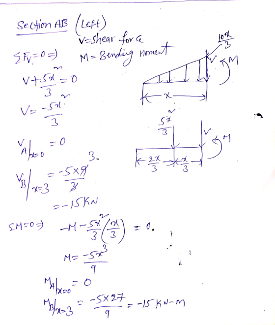
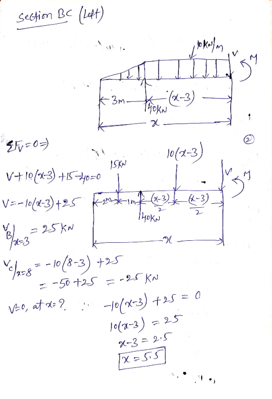
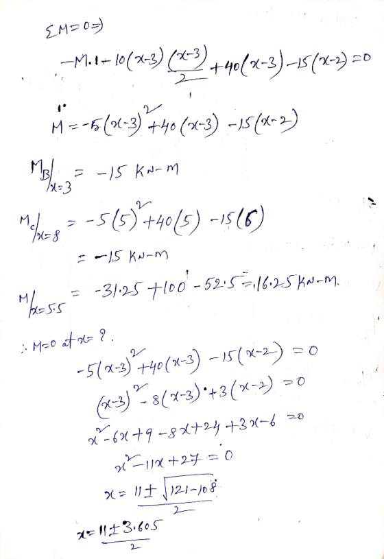
For the beam shown in Fig.3, q1= 10kN/m, Mo=15kN.m. a) Find all support reactions. b) Find the expressions for the shear force V and bending moment M. c) Draw the shear-force and bending-moment diagrams. Note that Mo acts at C, and dV/dx = -q, dM/dx = V
Homework Answers


Add Answer to:
For the beam shown in Fig.3, q1= 10kN/m, Mo=15kN.m. a) Find all support reactions. b) Find the expressions for the shear force V and bending moment M. c) Draw the shear-force and bending-moment diagra...
For the beam shown in Fig.3, q1= 10kN/m, Mo=15kN.m. a) Find all support reactions. b) Find the expressions for the shear force V and bending moment M. c) Draw the shear-force and bending-moment diagra...
 For the beam shown in Fig.3, q1= 10kN/m, Mo=15kN.m. a) Find all
support reactions. b) Find the expressions for the shear force V
and bending moment M. c) Draw the shear-force and bending-moment
diagrams. Note that Mo acts at C, and dV/dx = -q, dM/dx = V
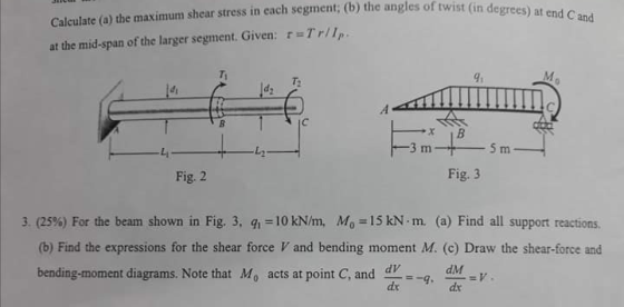
Calculate (a) the maximum shear stress in each segment; (b) the angles of twist (in d at the mid-span of the larger segment. Given: r-Trllp Ti 91 T: Fig. 2 Fig. 3 q,-10...
For the beam shown in Fig.3, q1= 10kN/m, Mo=15kN.m. a) Find all
support reactions. b) Find the expressions for the shear force V
and bending moment M. c) Draw the shear-force and bending-moment
diagrams. Note that Mo acts at C, and dV/dx = -q, dM/dx = V
Calculate (a) the maximum shear stress in each segment; (b) the angles of twist (in d at the mid-span of the larger segment. Given: r-Trllp Ti 91 T: Fig. 2 Fig. 3 q,-10...
To determine the reactive forces and moments acting on a beam;express the shear and bending...
 To determine the reactive forces and moments acting on a beam;
express the shear and bending moment as functions of their
positions along the beam; and construct shear and bending moment
diagrams. The cantilever beam shown is subjected to a moment at A
and a distributed load that acts over segment BC, and is fixed at
C. Determine the reactions at the support located at C. Then write
expressions for shear and bending moment as a function of their
positions...
To determine the reactive forces and moments acting on a beam;
express the shear and bending moment as functions of their
positions along the beam; and construct shear and bending moment
diagrams. The cantilever beam shown is subjected to a moment at A
and a distributed load that acts over segment BC, and is fixed at
C. Determine the reactions at the support located at C. Then write
expressions for shear and bending moment as a function of their
positions...
For the beam shown in Fig. 9.3, draw the shear force and bending moment diagrams. Use...
 For the beam shown in Fig. 9.3, draw the shear force and bending moment diagrams. Use the area method that relies on the relationships between loading and shear force and between shear force and bending moment. Indicate the slope of the shear force diagram at locations A, B, C, and D using the load information in Fig. 9.3. Indicate the slope of the bending moment diagram at the same four locations using information from the shear force diagram. | 6...
The cantilever beam shown is subjected to a moment at A and a distributed load that...
 The cantilever beam shown is subjected to a moment at A and a
distributed load that acts over segment BC, and is fixed at C.
Determine the reactions at the support located at C. Then write
expressions for shear and bending moment as a function of their
positions along the beam. Finally, use these expressions to
construct shear and bending moment diagrams.
Part A - Reactions at support C
Draw a free-body diagram of the beam on paper. Use your...
The cantilever beam shown is subjected to a moment at A and a
distributed load that acts over segment BC, and is fixed at C.
Determine the reactions at the support located at C. Then write
expressions for shear and bending moment as a function of their
positions along the beam. Finally, use these expressions to
construct shear and bending moment diagrams.
Part A - Reactions at support C
Draw a free-body diagram of the beam on paper. Use your...
Required Information For the beam shown, find the reactions at the supports and plot the shear-force...
 Required Information For the beam shown, find the reactions at the supports and plot the shear-force and bending-moment diagrams. V1 = 2 KN and V2 = 4 kN. NOTE: This is a multi-part question. Once an answer is submitted, you will be unable to return to this part. Vi V2 1.2 min А R2 Determine the values of the moments My, M2, and M3 In kNm. Provide values at all key points shown in the given shear-force and bending-moment diagrams....
a. Draw a free-body diagram for the beam shown above and derive expressions for the support...
 a. Draw a free-body diagram for the beam shown above and derive
expressions for the support reactions at A and B
b. Draw internal force (shear and bending moment) diagrams.
c. If a = 10 ft and M0 = 200 ft-lb, use the dimensions of the
beam cross-section, provided on the previous page, to compute the
maximum flexural and shear stresses on the beam cross-section.
d. If the allowable bending stress is 925 psi and the allowable
shear stress is...
a. Draw a free-body diagram for the beam shown above and derive
expressions for the support reactions at A and B
b. Draw internal force (shear and bending moment) diagrams.
c. If a = 10 ft and M0 = 200 ft-lb, use the dimensions of the
beam cross-section, provided on the previous page, to compute the
maximum flexural and shear stresses on the beam cross-section.
d. If the allowable bending stress is 925 psi and the allowable
shear stress is...
Use the graphical method to construct the shear-force and bending-moment diagrams for the beam shown. Label...
 Use the graphical method to construct the shear-force and bending-moment diagrams for the beam shown. Label all significant points on each diagram and identify the maximum moments along with their respective locations. Additionally: (a) Determine V and M in the beam at a point located 1.50 m to the right of B. (b) Determine Vand M in the beam at a point located 1.25 m to the left of D. Leta - 3.0m, b = 6.1 m,w = 38 kN/m,...
Problem 1: (30 points) Draw the shear force (V) and bending moment (M) diagrams for the...
 Problem 1: (30 points) Draw the shear force (V) and bending moment (M) diagrams for the beam AF given below. (B is a pin support, E is a roller support) Find the support reactions first. You are required to show the magnitude and location of all significant points. You don't have to find the equations defining the shear and moment diagrams unless necessary. However, indicate the order of all curves (e.g. 1" degree, 2nd degree, 3od degree). Ignore the depth...
Calculate.... 1. Calculate the support reactions and draw the axial force, shear force and bending moment...
 Calculate....
1. Calculate the support reactions and draw the axial force, shear force and bending moment diagrams for the beams and frame shown in Fig. 1, labelling all important values (such as, but not necessarily limited to, locations of points of inflection and values of shears and moments at supports, intersections and discontinuities). For the portal frame in li) assume there are points of inflection in the columns located 2.4m up from the ground and one in the beam midway...
Calculate....
1. Calculate the support reactions and draw the axial force, shear force and bending moment diagrams for the beams and frame shown in Fig. 1, labelling all important values (such as, but not necessarily limited to, locations of points of inflection and values of shears and moments at supports, intersections and discontinuities). For the portal frame in li) assume there are points of inflection in the columns located 2.4m up from the ground and one in the beam midway...
Shear and Bending Moment Diagrams Learning Goal: To determine the reactive forces and moments acting on...
 Shear and Bending Moment Diagrams
Learning Goal:
To determine the reactive forces and moments acting on a beam;
express the shear and bending moment as functions of their
positions along the beam; and construct shear and bending moment
diagrams.
The cantilever beam shown is subjected to a moment at A
and a distributed load that acts over segment BC, and is
fixed at C. Determine the reactions at the support located
at C. Then write expressions for shear and bending...
Shear and Bending Moment Diagrams
Learning Goal:
To determine the reactive forces and moments acting on a beam;
express the shear and bending moment as functions of their
positions along the beam; and construct shear and bending moment
diagrams.
The cantilever beam shown is subjected to a moment at A
and a distributed load that acts over segment BC, and is
fixed at C. Determine the reactions at the support located
at C. Then write expressions for shear and bending...
 For the beam shown in Fig.3, q1= 10kN/m, Mo=15kN.m. a) Find all
support reactions. b) Find the expressions for the shear force V
and bending moment M. c) Draw the shear-force and bending-moment
diagrams. Note that Mo acts at C, and dV/dx = -q, dM/dx = V
Calculate (a) the maximum shear stress in each segment; (b) the angles of twist (in d at the mid-span of the larger segment. Given: r-Trllp Ti 91 T: Fig. 2 Fig. 3 q,-10...
For the beam shown in Fig.3, q1= 10kN/m, Mo=15kN.m. a) Find all
support reactions. b) Find the expressions for the shear force V
and bending moment M. c) Draw the shear-force and bending-moment
diagrams. Note that Mo acts at C, and dV/dx = -q, dM/dx = V
Calculate (a) the maximum shear stress in each segment; (b) the angles of twist (in d at the mid-span of the larger segment. Given: r-Trllp Ti 91 T: Fig. 2 Fig. 3 q,-10...
 To determine the reactive forces and moments acting on a beam;
express the shear and bending moment as functions of their
positions along the beam; and construct shear and bending moment
diagrams. The cantilever beam shown is subjected to a moment at A
and a distributed load that acts over segment BC, and is fixed at
C. Determine the reactions at the support located at C. Then write
expressions for shear and bending moment as a function of their
positions...
To determine the reactive forces and moments acting on a beam;
express the shear and bending moment as functions of their
positions along the beam; and construct shear and bending moment
diagrams. The cantilever beam shown is subjected to a moment at A
and a distributed load that acts over segment BC, and is fixed at
C. Determine the reactions at the support located at C. Then write
expressions for shear and bending moment as a function of their
positions...
 For the beam shown in Fig. 9.3, draw the shear force and bending moment diagrams. Use the area method that relies on the relationships between loading and shear force and between shear force and bending moment. Indicate the slope of the shear force diagram at locations A, B, C, and D using the load information in Fig. 9.3. Indicate the slope of the bending moment diagram at the same four locations using information from the shear force diagram. | 6...
 The cantilever beam shown is subjected to a moment at A and a
distributed load that acts over segment BC, and is fixed at C.
Determine the reactions at the support located at C. Then write
expressions for shear and bending moment as a function of their
positions along the beam. Finally, use these expressions to
construct shear and bending moment diagrams.
Part A - Reactions at support C
Draw a free-body diagram of the beam on paper. Use your...
The cantilever beam shown is subjected to a moment at A and a
distributed load that acts over segment BC, and is fixed at C.
Determine the reactions at the support located at C. Then write
expressions for shear and bending moment as a function of their
positions along the beam. Finally, use these expressions to
construct shear and bending moment diagrams.
Part A - Reactions at support C
Draw a free-body diagram of the beam on paper. Use your...
 Required Information For the beam shown, find the reactions at the supports and plot the shear-force and bending-moment diagrams. V1 = 2 KN and V2 = 4 kN. NOTE: This is a multi-part question. Once an answer is submitted, you will be unable to return to this part. Vi V2 1.2 min А R2 Determine the values of the moments My, M2, and M3 In kNm. Provide values at all key points shown in the given shear-force and bending-moment diagrams....
 a. Draw a free-body diagram for the beam shown above and derive
expressions for the support reactions at A and B
b. Draw internal force (shear and bending moment) diagrams.
c. If a = 10 ft and M0 = 200 ft-lb, use the dimensions of the
beam cross-section, provided on the previous page, to compute the
maximum flexural and shear stresses on the beam cross-section.
d. If the allowable bending stress is 925 psi and the allowable
shear stress is...
a. Draw a free-body diagram for the beam shown above and derive
expressions for the support reactions at A and B
b. Draw internal force (shear and bending moment) diagrams.
c. If a = 10 ft and M0 = 200 ft-lb, use the dimensions of the
beam cross-section, provided on the previous page, to compute the
maximum flexural and shear stresses on the beam cross-section.
d. If the allowable bending stress is 925 psi and the allowable
shear stress is...
 Use the graphical method to construct the shear-force and bending-moment diagrams for the beam shown. Label all significant points on each diagram and identify the maximum moments along with their respective locations. Additionally: (a) Determine V and M in the beam at a point located 1.50 m to the right of B. (b) Determine Vand M in the beam at a point located 1.25 m to the left of D. Leta - 3.0m, b = 6.1 m,w = 38 kN/m,...
 Problem 1: (30 points) Draw the shear force (V) and bending moment (M) diagrams for the beam AF given below. (B is a pin support, E is a roller support) Find the support reactions first. You are required to show the magnitude and location of all significant points. You don't have to find the equations defining the shear and moment diagrams unless necessary. However, indicate the order of all curves (e.g. 1" degree, 2nd degree, 3od degree). Ignore the depth...
 Calculate....
1. Calculate the support reactions and draw the axial force, shear force and bending moment diagrams for the beams and frame shown in Fig. 1, labelling all important values (such as, but not necessarily limited to, locations of points of inflection and values of shears and moments at supports, intersections and discontinuities). For the portal frame in li) assume there are points of inflection in the columns located 2.4m up from the ground and one in the beam midway...
Calculate....
1. Calculate the support reactions and draw the axial force, shear force and bending moment diagrams for the beams and frame shown in Fig. 1, labelling all important values (such as, but not necessarily limited to, locations of points of inflection and values of shears and moments at supports, intersections and discontinuities). For the portal frame in li) assume there are points of inflection in the columns located 2.4m up from the ground and one in the beam midway...
 Shear and Bending Moment Diagrams
Learning Goal:
To determine the reactive forces and moments acting on a beam;
express the shear and bending moment as functions of their
positions along the beam; and construct shear and bending moment
diagrams.
The cantilever beam shown is subjected to a moment at A
and a distributed load that acts over segment BC, and is
fixed at C. Determine the reactions at the support located
at C. Then write expressions for shear and bending...
Shear and Bending Moment Diagrams
Learning Goal:
To determine the reactive forces and moments acting on a beam;
express the shear and bending moment as functions of their
positions along the beam; and construct shear and bending moment
diagrams.
The cantilever beam shown is subjected to a moment at A
and a distributed load that acts over segment BC, and is
fixed at C. Determine the reactions at the support located
at C. Then write expressions for shear and bending...
Most questions answered within 3 hours.
-
Need help with coming up with competitive strategies in
the furniture retail industry. Any help would...
asked 1 minute ago -
how to select perpendicular gd&t tolerance value
using IT tolerance. and gave example
asked 8 minutes ago -
plz explain: A sound that changes pressure from 100 mPa to 10
mPa has a change...
asked 7 minutes ago -
What is the measured air concentration from a sample that has 38
μg of contaminant when...
asked 27 minutes ago -
In support of the argument that we have free will, what are the
implications of seemingly...
asked 28 minutes ago -
Share your thoughts concerning the pros and cons of using
natural products as anticancer agents. (please...
asked 37 minutes ago -
Describe in detail how your own actions reflect the
ideas shared in the discussion, and relate...
asked 42 minutes ago -
Name and clearly describe one technique for determining the age
of fossils in geological context. Are...
asked 55 minutes ago -
A ball is thrown with an initial velocity of 20.0 m/s at an
angle of 35.00...
asked 49 minutes ago -
When assessing pension risk, analysts compute ratios for both
long- and short-term risk. Which statement below...
asked 48 minutes ago -
What is the relativistic momentum of a proton traveling at
0.990c?
A. 3.55E–18 kg·m/s
B. 3.52E–18...
asked 57 minutes ago -
Question 1: B cells secrete these types of immunoglobulin
antibodies. Choose all correct.
1. IgD
2....
asked 1 hour ago