question about mechanics of materials
Homework Answers

Add Answer to:
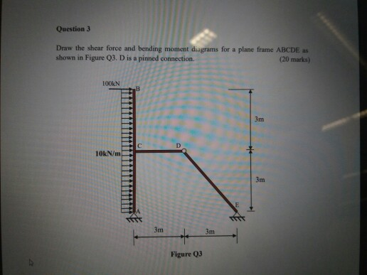
question about mechanics of materials i Question 3 Draw the shear force and bending moment diagrams for a plane frame ABCDE as shown in Figure Q3. D is a pinned connection. frame ABCDE as plane (2...
Draw the axial force, shear, and moment diagrams for the frame shown below. Points A, C, and D act as pinned connections, while point B is a fixed connection.
 Draw the axial force, shear, and moment diagrams for the frame shown below. Points A, C, and D act as pinned connections, while point B is a fixed connection.
4. For the beam and loading shown, draw the shear force and bending moment diagrams and...
 4. For the beam and loading shown, draw the shear force and bending moment diagrams and determine the maximum bending and shear force and their locations. 20 KN 40 KN B D 250 mm |--2.5 m- 3m-4-2 m 80 mm 5. For the beam and loading shown, draw the shear force and bending moment diagrams and determine the maximum bending and shear force and their locations. 50 KN
Normal force N, shear force V and bending moment M for the frame shown in the...
 Normal force N, shear force V and bending moment M for
the frame shown in the figure
The method of cutting diagrams (using 8 cutting points in the
figure and their calculations
draw on paper).
please help.course name is building static 1.
15 kN/m 20 kNm 5 +6 T 2 m 3m a 20KN 7 B 2 A 8 HA 30 kN tu 3m . 2 4 3
Normal force N, shear force V and bending moment M for
the frame shown in the figure
The method of cutting diagrams (using 8 cutting points in the
figure and their calculations
draw on paper).
please help.course name is building static 1.
15 kN/m 20 kNm 5 +6 T 2 m 3m a 20KN 7 B 2 A 8 HA 30 kN tu 3m . 2 4 3
Q1. Draw the shear force and bending moment diagrams for the following cantilever beam
 Q1. Draw the shear force and bending moment diagrams for the following cantilever beam (10 marks). Q2. Draw the shear force and bending moment diagrams for the following simply supported beam (10 marks). Q3. Draw the shear force and bending moment diagrams for the following simply supported beam with cantilever extension (15 marks). Q4. Draw the shear force and bending moment diagrams for the following compound beam (15 marks).
A two-dimensional two-pinned portal frame ABCDE is pinned to rigid supports at positions A and E,...
 A two-dimensional two-pinned portal frame ABCDE is pinned to rigid supports at positions A and E, and a concentrated couple of 350 kNm acting clockwise is applied at C as shown in Figure Q3. All members of the portal frame are made from the same steel section. 350 kNm 6 m EI CONSTANT FOR ALL MEMBERS 6 m 4 m Fgure Q3 Determine, using methods incorporating strain energy where appropriate. the magnitude and direction of the vertical and horizontal reactions...
Draw the shear force and bending moment diagrams for a cantilever beam as shown in Figure 3.
 Draw the shear force and bending moment diagrams for a cantilever beam as shown in Figure 3.
A frame structure is shown in Figure 1, in which points A, B and C are all pins (a) Draw the shear and moment diagrams...
 A frame structure is shown in Figure 1, in which points A, B and C are all pins (a) Draw the shear and moment diagrams for the frame, and determine the shear and moment at points D and E [20 marks] (b) Calculate the horizontal deflection of the frame at joint F use virtual-work. EI for all members are the same and is a constant. [20 marks] 0.25 m 0.75 m C D 0.75 m 0.75 m 00 N/m 60...
find 1) Draw shear force and bending moment diagrams for the beams subjected to the loadings...
 find
1) Draw shear force and bending moment diagrams for the beams subjected to the loadings shown below. Please show all your work SEN 25 N/m 45KM 10KN KN 15 2m 1 Im 2 3 m
find
1) Draw shear force and bending moment diagrams for the beams subjected to the loadings shown below. Please show all your work SEN 25 N/m 45KM 10KN KN 15 2m 1 Im 2 3 m
For the beam shown in Fig. 9.3, draw the shear force and bending moment diagrams. Use...
 For the beam shown in Fig. 9.3, draw the shear force and bending moment diagrams. Use the area method that relies on the relationships between loading and shear force and between shear force and bending moment. Indicate the slope of the shear force diagram at locations A, B, C, and D using the load information in Fig. 9.3. Indicate the slope of the bending moment diagram at the same four locations using information from the shear force diagram. | 6...
 4. For the beam and loading shown, draw the shear force and bending moment diagrams and determine the maximum bending and shear force and their locations. 20 KN 40 KN B D 250 mm |--2.5 m- 3m-4-2 m 80 mm 5. For the beam and loading shown, draw the shear force and bending moment diagrams and determine the maximum bending and shear force and their locations. 50 KN
 Normal force N, shear force V and bending moment M for
the frame shown in the figure
The method of cutting diagrams (using 8 cutting points in the
figure and their calculations
draw on paper).
please help.course name is building static 1.
15 kN/m 20 kNm 5 +6 T 2 m 3m a 20KN 7 B 2 A 8 HA 30 kN tu 3m . 2 4 3
Normal force N, shear force V and bending moment M for
the frame shown in the figure
The method of cutting diagrams (using 8 cutting points in the
figure and their calculations
draw on paper).
please help.course name is building static 1.
15 kN/m 20 kNm 5 +6 T 2 m 3m a 20KN 7 B 2 A 8 HA 30 kN tu 3m . 2 4 3
 A two-dimensional two-pinned portal frame ABCDE is pinned to rigid supports at positions A and E, and a concentrated couple of 350 kNm acting clockwise is applied at C as shown in Figure Q3. All members of the portal frame are made from the same steel section. 350 kNm 6 m EI CONSTANT FOR ALL MEMBERS 6 m 4 m Fgure Q3 Determine, using methods incorporating strain energy where appropriate. the magnitude and direction of the vertical and horizontal reactions...
 A frame structure is shown in Figure 1, in which points A, B and C are all pins (a) Draw the shear and moment diagrams for the frame, and determine the shear and moment at points D and E [20 marks] (b) Calculate the horizontal deflection of the frame at joint F use virtual-work. EI for all members are the same and is a constant. [20 marks] 0.25 m 0.75 m C D 0.75 m 0.75 m 00 N/m 60...
 find
1) Draw shear force and bending moment diagrams for the beams subjected to the loadings shown below. Please show all your work SEN 25 N/m 45KM 10KN KN 15 2m 1 Im 2 3 m
find
1) Draw shear force and bending moment diagrams for the beams subjected to the loadings shown below. Please show all your work SEN 25 N/m 45KM 10KN KN 15 2m 1 Im 2 3 m
 For the beam shown in Fig. 9.3, draw the shear force and bending moment diagrams. Use the area method that relies on the relationships between loading and shear force and between shear force and bending moment. Indicate the slope of the shear force diagram at locations A, B, C, and D using the load information in Fig. 9.3. Indicate the slope of the bending moment diagram at the same four locations using information from the shear force diagram. | 6...
Most questions answered within 3 hours.
-
Accent Software faces the following conditions. All of these
support Accent’s use of a market-penetration pricing...
asked 8 minutes ago -
A mathematically inclined friend emails you the following
instructions: "Meet me in the cafeteria the first...
asked 11 minutes ago -
A monopoly sells in two countries . The demand curves in the two
countries are p1...
asked 1 hour ago -
A .15kg rubber ball is bounced off a wall. Before hitting the
wall, the ball moves...
asked 1 hour ago -
A manufacturing company preparing to build a new plant is
considering three potential locations for it....
asked 1 hour ago -
B. If compound Y has approximately the same values of solubility
in toluene as compound X,...
asked 2 hours ago -
Oscar Inc. has inventory in Japan valued at 39,051,000 Yen one
year ago. One year ago...
asked 2 hours ago -
If Canada suffered from "fundamental disequilibrium," and its
government choose not to devalue its currency, a...
asked 2 hours ago -
4. How many input & output Key Value Pairs are passed into,
and emitted out of...
asked 2 hours ago -
Why would your heart not function well if constructed of
skeletal muscle? What is the particular...
asked 2 hours ago -
Please respond to this essay question in full essay form for
Chemistry 1102 Organic and Biochemistry:...
asked 2 hours ago -
Determine the head loss and velocity of flow in a water supply main
of 15.0 cm...
asked 2 hours ago