
Homework Answers

Add Answer to:
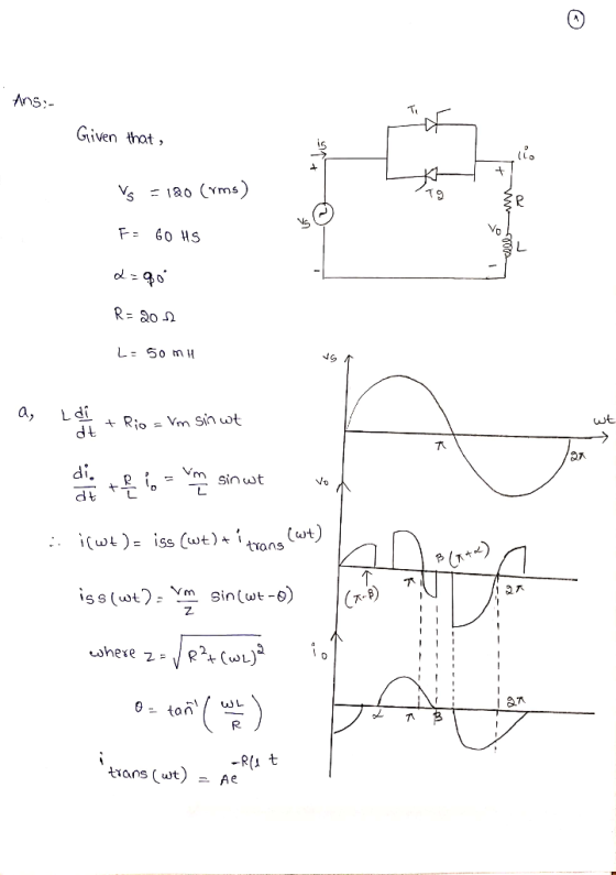
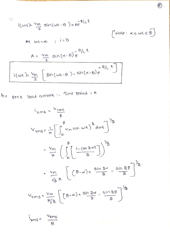
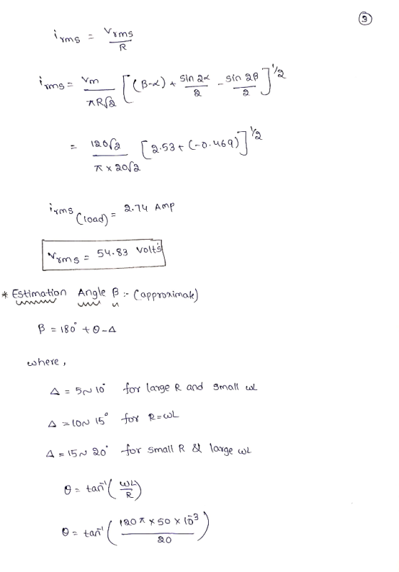
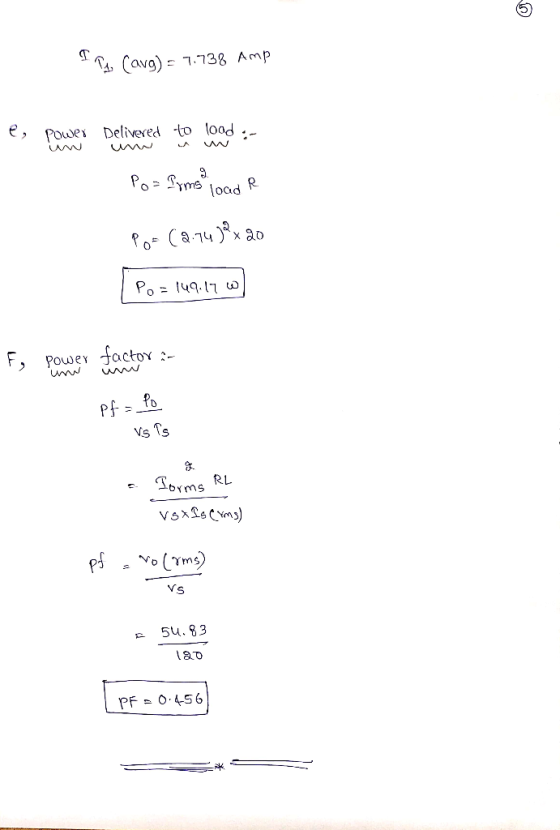
clear handwrite and step by step solution please thank you in advance Q2. For the single-phase voltage controller of Fig. 2, the source is 120 Vrms at 60 Hz, andthe load is a series Rしcombinatio...
A single-phase half-wave ac voltage controller feeds a load of R = 40 Ω with (maximum...
A single-phase half-wave ac voltage controller feeds a load of R = 40 Ω with (maximum voltage of 230V), 50 Hz. Firing angle of thyristor is 60°. Determine (a) rms value of output voltage (b) power delivered to load and input pf and (c) average input current. (a) The rms value of load voltage. And repeat the above for A single phase Full-wave ac voltage controller?
Questions 1 to 3 relate to a three-phase SCR rectifier supplied from a 415 Vrms, 50 Hz ac source. For a 100 Ω resistive load, determine the peak, minimum and average load current for SCR firing angle...
 Questions 1 to 3 relate to a three-phase SCR rectifier supplied from a 415 Vrms, 50 Hz ac source. For a 100 Ω resistive load, determine the peak, minimum and average load current for SCR firing angles of: (a) a-0° (5.87 A, 5.08 A, 5.6 A) (b) α = 45° (5.67 A, 1.52 A, 3.96 A) (c) α-70° (4.5 A, 0 A, 2.0 A) How will your answers change if a very large inductance (zero resistance) is added in series...
The single-phase full converter as shown in Figure 8-1 has an RL load having L =...
 The single-phase full converter as shown in Figure 8-1 has an RL load having L = 5 mH, R-0.8 Ω, and E -0 V. The input voltage is Vs = 120 V at(rms) 60 Hz. The delay angle or-α-300 Calculate the performance parameters. Assume ideal thyristor switches. the rms thyristor current IR Figure 8-1 Single-Phase Full Converter T1 T4 太T2 0
A 240 volts 50 Hz single phase ac source supplies a series load consisting of a...
A 240 volts 50 Hz single phase ac source supplies a series load consisting of a resistor (40 ohms), a reactor (127.324 mH) and a capacitor (318.3 μF). Calculate the current and real power delivered by the source. Calculate the voltage developed across each the three load circuit components.
step by step solution please thank you in advance Q1. The single-phase fully-controlled rectifier shown in...
 step by step solution please
thank you in advance
Q1. The single-phase fully-controlled rectifier shown in Fig. 1, is operated from a 120 V rms supply and feeds a highly inductive load with R-102 a) Sketch the load voltage (Vo) and then find its average (Vde) as a function of a b) The firing angle is α-450 and the load current is la-15 A. Find the average power supplied to the load c) Sketch the source current (is) for α-450...
step by step solution please
thank you in advance
Q1. The single-phase fully-controlled rectifier shown in Fig. 1, is operated from a 120 V rms supply and feeds a highly inductive load with R-102 a) Sketch the load voltage (Vo) and then find its average (Vde) as a function of a b) The firing angle is α-450 and the load current is la-15 A. Find the average power supplied to the load c) Sketch the source current (is) for α-450...
A three phase full-wave AC controller in Figure Q5(a) is supplied to a system with Y...
 A three phase full-wave AC controller in Figure Q5(a) is supplied to a system with Y connected load system. The load consists of R = 100 and L = 0.01 mH which are connected in series between them. The line-to-line input voltage is given as 208 V with 50 Hz and the delay angle is given as a = 271/3. (1) Calculate the rms value of output phase voltage. (3 marks) (ii) Determine the power factor at output based on...
A controlled full bridge recetifier Ti Ty Ts T: Figure P5 A controlled full-wave bridge converter has a source of 120 Vrms at 60 Hz, R-25 Ω, L- 10 mH. Assuming that the load constant voltage sourc...
 A controlled full bridge recetifier
Ti Ty Ts T: Figure P5 A controlled full-wave bridge converter has a source of 120 Vrms at 60 Hz, R-25 Ω, L- 10 mH. Assuming that the load constant voltage source E = OV and the gate pulse firing angle is α-45°, determine whether the converter operates in the continuous (CCM) or discontinuous (DCM) conduction mode;
Ti Ty Ts T: Figure P5 A controlled full-wave bridge converter has a source of 120 Vrms at...
A controlled full bridge recetifier
Ti Ty Ts T: Figure P5 A controlled full-wave bridge converter has a source of 120 Vrms at 60 Hz, R-25 Ω, L- 10 mH. Assuming that the load constant voltage source E = OV and the gate pulse firing angle is α-45°, determine whether the converter operates in the continuous (CCM) or discontinuous (DCM) conduction mode;
Ti Ty Ts T: Figure P5 A controlled full-wave bridge converter has a source of 120 Vrms at...
b. Consider the single-phase fully controlled of thyristor bridge rectifier supplies a load consists of R-L...
 b. Consider the single-phase fully controlled of thyristor bridge rectifier supplies a load consists of R-L load and Vee in series as shown in Figure Q2 (b). The parameters for this circuit are as follows: supply voltage is 120 Vrms at 60 Hz, DC voltage, Voe equal to 10 v. i. Sketch the waveforms for output voltage, thyristor current, diode current and output current (CO2: PO2 - 5 marks) Calculate the output voltage, Va at a = Tt/2. (CO2: PO2...
Series and parallel RL and RC circuits with an AC source. A 60 Hz voltage source...
 Series and parallel RL and RC circuits with an AC source. A 60 Hz voltage source has an amplitude of VT-120 V. For the following problems, compute the indicated phasors including both magnitudes and phase angles, and sketch the phasor diagrams (no submission) Q1. The source is connected across a series RL ac circuit with R 7.8 Ohm and XL = ωし= 5.1 Ohm. 1a) Find the magnitude of impedance of the series combination (Unit: Ohm) Submit Answer Tries 0/3...
1. A resistor R and capacitor care connected in series with an AC voltage source with...
 1. A resistor R and capacitor care connected in series with an AC voltage source with frequency f and maximum voltage Vo. a. Find the complex impedance (in the form Z = R + jX). If the impedance is written in polar form (Z = Zejº), find expressions for Z and Ⓡ. Write your answers in terms of the variables R, C, and o(= 21f). b. If the voltage source is described by the phasor V = V, ejwt, and...
 Questions 1 to 3 relate to a three-phase SCR rectifier supplied from a 415 Vrms, 50 Hz ac source. For a 100 Ω resistive load, determine the peak, minimum and average load current for SCR firing angles of: (a) a-0° (5.87 A, 5.08 A, 5.6 A) (b) α = 45° (5.67 A, 1.52 A, 3.96 A) (c) α-70° (4.5 A, 0 A, 2.0 A) How will your answers change if a very large inductance (zero resistance) is added in series...
 The single-phase full converter as shown in Figure 8-1 has an RL load having L = 5 mH, R-0.8 Ω, and E -0 V. The input voltage is Vs = 120 V at(rms) 60 Hz. The delay angle or-α-300 Calculate the performance parameters. Assume ideal thyristor switches. the rms thyristor current IR Figure 8-1 Single-Phase Full Converter T1 T4 太T2 0
 step by step solution please
thank you in advance
Q1. The single-phase fully-controlled rectifier shown in Fig. 1, is operated from a 120 V rms supply and feeds a highly inductive load with R-102 a) Sketch the load voltage (Vo) and then find its average (Vde) as a function of a b) The firing angle is α-450 and the load current is la-15 A. Find the average power supplied to the load c) Sketch the source current (is) for α-450...
step by step solution please
thank you in advance
Q1. The single-phase fully-controlled rectifier shown in Fig. 1, is operated from a 120 V rms supply and feeds a highly inductive load with R-102 a) Sketch the load voltage (Vo) and then find its average (Vde) as a function of a b) The firing angle is α-450 and the load current is la-15 A. Find the average power supplied to the load c) Sketch the source current (is) for α-450...
 A three phase full-wave AC controller in Figure Q5(a) is supplied to a system with Y connected load system. The load consists of R = 100 and L = 0.01 mH which are connected in series between them. The line-to-line input voltage is given as 208 V with 50 Hz and the delay angle is given as a = 271/3. (1) Calculate the rms value of output phase voltage. (3 marks) (ii) Determine the power factor at output based on...
 A controlled full bridge recetifier
Ti Ty Ts T: Figure P5 A controlled full-wave bridge converter has a source of 120 Vrms at 60 Hz, R-25 Ω, L- 10 mH. Assuming that the load constant voltage source E = OV and the gate pulse firing angle is α-45°, determine whether the converter operates in the continuous (CCM) or discontinuous (DCM) conduction mode;
Ti Ty Ts T: Figure P5 A controlled full-wave bridge converter has a source of 120 Vrms at...
A controlled full bridge recetifier
Ti Ty Ts T: Figure P5 A controlled full-wave bridge converter has a source of 120 Vrms at 60 Hz, R-25 Ω, L- 10 mH. Assuming that the load constant voltage source E = OV and the gate pulse firing angle is α-45°, determine whether the converter operates in the continuous (CCM) or discontinuous (DCM) conduction mode;
Ti Ty Ts T: Figure P5 A controlled full-wave bridge converter has a source of 120 Vrms at...
 b. Consider the single-phase fully controlled of thyristor bridge rectifier supplies a load consists of R-L load and Vee in series as shown in Figure Q2 (b). The parameters for this circuit are as follows: supply voltage is 120 Vrms at 60 Hz, DC voltage, Voe equal to 10 v. i. Sketch the waveforms for output voltage, thyristor current, diode current and output current (CO2: PO2 - 5 marks) Calculate the output voltage, Va at a = Tt/2. (CO2: PO2...
 Series and parallel RL and RC circuits with an AC source. A 60 Hz voltage source has an amplitude of VT-120 V. For the following problems, compute the indicated phasors including both magnitudes and phase angles, and sketch the phasor diagrams (no submission) Q1. The source is connected across a series RL ac circuit with R 7.8 Ohm and XL = ωし= 5.1 Ohm. 1a) Find the magnitude of impedance of the series combination (Unit: Ohm) Submit Answer Tries 0/3...
 1. A resistor R and capacitor care connected in series with an AC voltage source with frequency f and maximum voltage Vo. a. Find the complex impedance (in the form Z = R + jX). If the impedance is written in polar form (Z = Zejº), find expressions for Z and Ⓡ. Write your answers in terms of the variables R, C, and o(= 21f). b. If the voltage source is described by the phasor V = V, ejwt, and...
Most questions answered within 3 hours.
-
Write a program to solve the Josephus problem, with the following
modification:
Sample Input:
./a.out n...
asked 1 hour ago -
At the start of a CD it is spinning at a rate of 525 rpm
(revolutions...
asked 2 hours ago -
4. Without doing any calculations, predict whether the observed
∆T would increase, decrease or remain the...
asked 3 hours ago -
Based on the range, which of the following sets of scores has
the greatest variability? 3,...
asked 4 hours ago -
Ripples in a pond travel at a velocity of 3 m/s with one peak
passing a...
asked 4 hours ago -
A man stands on the roof of a building of height 13.0 mm and
throws a...
asked 4 hours ago -
The extent to which assets are financed by borrowed funds and
other liabilities is indicated by:...
asked 5 hours ago -
Explain in detail
Germany is the fifth largest economy
explain what goods and services Germany specializes...
asked 5 hours ago -
The density of platinum is 21.45 g/mL. If a cube of platinum
with a mass of...
asked 5 hours ago -
Accounts Receivable
Sales
A/R Posting
Extended Sales Invoice
Packing Slip
Compare invoice to packing slip 2...
asked 5 hours ago -
Michaella, age 23, is a full-time law student and is claimed by
her parents as a...
asked 5 hours ago -
Why are polymers not typically casted into products?
asked 6 hours ago