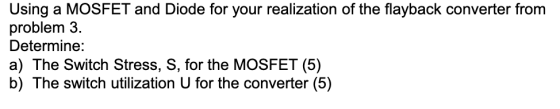
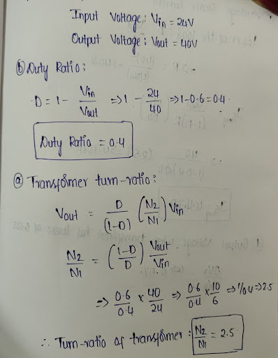
Design a flyback converter for an input of 24 volts and an output of 40 volts. Assume a 40W load and keep the blocking voltage for the transistor to < 26 volts.
For your design determine:
a) The transformer turn ratio n (5).
b) The duty cycle D (5).
c) The average source current (3).
d) The output voltage of the converter when we include the effect of a transformer winding losses as 0.05 ohms (7).
Using a MOSFET and Diode for your realization of the flayback converter
Determine:
a) The Switch Stress, S, for the MOSFET (5)
b) The switch utilizationU for the converter (5)
Any help appreciated

Homework Answers
Add Answer to:
Design a flyback converter for an input of 24 volts and an output of 40 volts. Assume a 40W load and keep the blocking voltage for the transistor to < 26 volts. For your design determine: a) The tr...
Design a flyback converter for an input of 24 volts and an output of 40 volts. Assume a 40W load and keep the blocking voltage for the transistor to < 26 volts, For your design determine: a) The t...
 Design a flyback converter for an input of 24 volts and an output of 40 volts. Assume a 40W load and keep the blocking voltage for the transistor to < 26 volts, For your design determine: a) The transformer turn ratio n (5) b) The duty cycle D (5). c) The average source current (3). d) The output voltage of the converter when we include the effect of a transformer winding losses as 0.05 ohms (7)
Design a flyback converter...
Design a flyback converter for an input of 24 volts and an output of 40 volts. Assume a 40W load and keep the blocking voltage for the transistor to < 26 volts, For your design determine: a) The transformer turn ratio n (5) b) The duty cycle D (5). c) The average source current (3). d) The output voltage of the converter when we include the effect of a transformer winding losses as 0.05 ohms (7)
Design a flyback converter...
stuck on part d please show steps and explantion Design a flyback converter for an input of 24 volts and an output of 40 volts. Assume a 40W load and keep the blocking voltage for the transistor t...
 stuck on part d please show steps and explantion
Design a flyback converter for an input of 24 volts and an output of 40 volts. Assume a 40W load and keep the blocking voltage for the transistor to < 26 volts. For your design determine: a) The transformer turn ratio n (5) b) The duty cycle D (5) c) The average source current (3). d) The output voltage of the converter when we include the effect of a transformer winding...
stuck on part d please show steps and explantion
Design a flyback converter for an input of 24 volts and an output of 40 volts. Assume a 40W load and keep the blocking voltage for the transistor to < 26 volts. For your design determine: a) The transformer turn ratio n (5) b) The duty cycle D (5) c) The average source current (3). d) The output voltage of the converter when we include the effect of a transformer winding...
of CM with Consider the flyback converter with DC input voltage Vd of 48v. The output...
 of CM with Consider the flyback converter with DC input voltage Vd of 48v. The output voltage is regulated to 5V and the turn's ratio transformer is considered as 6:1. The magnetizing inductance of the transformer is 150?H The converter is operated in C a switching frequency of 200 kHz with the load power of 30W. Assuming the converter to be lossless, calculate b. switch voltage stress neglecting the leakage inductance of the transformer
Design a boost converter power stage to the following specification: Input voltage Output voltage: Output voltage...
 Design a boost converter power stage to the following specification: Input voltage Output voltage: Output voltage ripple:max 20mV Load power: Switching frequency: 15kHz 110-125V 300V 1.5kW Calculate: (i) Maximum duty cycle (ii) Minimum duty cycle (iii) Average diode current (iv) Assuming the Rds(on) of the MOSFET is 0.01 Ω, and the diode forward voltage is 0.8V, calculate the approximate efficiency of the circuit. 2. A switching power supply shown in the circuit below has its switch driven by a signal...
I want to solve this problem step by step 1. (35 points) Switch mode DC / DC Converters. a. (15 points) Design a flyback DC/DC power converter to the following specifications. Assume ideal compone...
 I want to solve this problem step by step
1. (35 points) Switch mode DC / DC Converters. a. (15 points) Design a flyback DC/DC power converter to the following specifications. Assume ideal components. Input Voltage Output Voltage Output Power Switching frequency Maximum Current Ripple in the filter inductor Output ripple voltage: Continuous conduction 170 VDC 12 VDC 40 Watts 750 kHz 1.2 Amps Your answer should include a circuit diagram with each energy storage element labeled with its value....
I want to solve this problem step by step
1. (35 points) Switch mode DC / DC Converters. a. (15 points) Design a flyback DC/DC power converter to the following specifications. Assume ideal components. Input Voltage Output Voltage Output Power Switching frequency Maximum Current Ripple in the filter inductor Output ripple voltage: Continuous conduction 170 VDC 12 VDC 40 Watts 750 kHz 1.2 Amps Your answer should include a circuit diagram with each energy storage element labeled with its value....
To design a high efficiency d.c., to d.c power converter with the given specifications min 10V max 15V nominal (regulated) 8V Input voltage: Output voltage: Nominal load current: 4A Inductor current...
 To design a high efficiency d.c., to d.c power converter with the given specifications min 10V max 15V nominal (regulated) 8V Input voltage: Output voltage: Nominal load current: 4A Inductor current ripple: 0.1A max Switching frequency: 30 kHz Output voltage ripple: 20 mV Define a suitable power circuit topology to meet the above specification? Sketch a circuit diagram of the chosen power circuit topology (a) Define the minimum and maximum duty cycles assuming that the control circuit keeps the output...
1. (35 points) Switch mode DC DC Converters. a. (15 points) Design a flyback DC/DC power converter to the following specifications. Assume ideal components Input Voltage Output Voltage Output Powe...
 1. (35 points) Switch mode DC DC Converters. a. (15 points) Design a flyback DC/DC power converter to the following specifications. Assume ideal components Input Voltage Output Voltage Output Power Switching frequency Maximum Current Ripple in the filter inductor Output ripple voltage: Continuous conduction 170 VDC 12 VDC 40 Watts 750 kHz 1.2 Amps Your answer should include a circuit diagram with each energy storage element labeled with its value. Label the transformer turns ratio.
1. (35 points) Switch mode...
1. (35 points) Switch mode DC DC Converters. a. (15 points) Design a flyback DC/DC power converter to the following specifications. Assume ideal components Input Voltage Output Voltage Output Power Switching frequency Maximum Current Ripple in the filter inductor Output ripple voltage: Continuous conduction 170 VDC 12 VDC 40 Watts 750 kHz 1.2 Amps Your answer should include a circuit diagram with each energy storage element labeled with its value. Label the transformer turns ratio.
1. (35 points) Switch mode...
Problem 2 A 1.5 volt energy source is to used to power a 5 volt, 1 amp load. A buck-boost converter is used for this application. A suitable transistor is found with an on-resistance of 35 mQ, and a...
 Problem 2 A 1.5 volt energy source is to used to power a 5 volt, 1 amp load. A buck-boost converter is used for this application. A suitable transistor is found with an on-resistance of 35 mQ, and a Schottky diode is found with a forward drop of 0.5 volts. The on resistance of the Schottky diode may be ignored. The circuit is shown in the following figure. 1 A 100 HH 5 V Load 1.5 V DT T f,...
In this part of the term paper, design a single-phase switch-mode DC power supply with a forward ...
 In this part of the term paper, design a single-phase switch-mode DC power supply with a forward converter. Provide answers to the questions below Please combine the single-phase full-wave rectifier from part two of your term paper with a forward converter to produce a switch-mode DC power supply, as shown below. The output of the bridge rectifier serves as input to the forward converter L1 Np: N BH621BH62 D, V1 Load C1 100p 45 Vrms D3 BH62 18H62 D4 Control...
1. to design a high efficiency d.c. to d.c. power converter with the given specifications Input v...
 1. to design a high efficiency d.c. to d.c. power converter with the given specifications Input voltage Output voltage Nominal load current: 4A Inductor current ripple: 0.1A max Switching frequency: 30 kHz Output voltage ripple: 20 mV min 10V max 15V nominal (regulated) 8V Define a suitable power circuit topology to meet the above specification Sketch a circuit diagram of the chosen power circuit topology (a) Define the minimum and maximum duty cycles assuming that the control circuit keeps the...
 Design a flyback converter for an input of 24 volts and an output of 40 volts. Assume a 40W load and keep the blocking voltage for the transistor to < 26 volts, For your design determine: a) The transformer turn ratio n (5) b) The duty cycle D (5). c) The average source current (3). d) The output voltage of the converter when we include the effect of a transformer winding losses as 0.05 ohms (7)
Design a flyback converter...
Design a flyback converter for an input of 24 volts and an output of 40 volts. Assume a 40W load and keep the blocking voltage for the transistor to < 26 volts, For your design determine: a) The transformer turn ratio n (5) b) The duty cycle D (5). c) The average source current (3). d) The output voltage of the converter when we include the effect of a transformer winding losses as 0.05 ohms (7)
Design a flyback converter...
 stuck on part d please show steps and explantion
Design a flyback converter for an input of 24 volts and an output of 40 volts. Assume a 40W load and keep the blocking voltage for the transistor to < 26 volts. For your design determine: a) The transformer turn ratio n (5) b) The duty cycle D (5) c) The average source current (3). d) The output voltage of the converter when we include the effect of a transformer winding...
stuck on part d please show steps and explantion
Design a flyback converter for an input of 24 volts and an output of 40 volts. Assume a 40W load and keep the blocking voltage for the transistor to < 26 volts. For your design determine: a) The transformer turn ratio n (5) b) The duty cycle D (5) c) The average source current (3). d) The output voltage of the converter when we include the effect of a transformer winding...
 of CM with Consider the flyback converter with DC input voltage Vd of 48v. The output voltage is regulated to 5V and the turn's ratio transformer is considered as 6:1. The magnetizing inductance of the transformer is 150?H The converter is operated in C a switching frequency of 200 kHz with the load power of 30W. Assuming the converter to be lossless, calculate b. switch voltage stress neglecting the leakage inductance of the transformer
 Design a boost converter power stage to the following specification: Input voltage Output voltage: Output voltage ripple:max 20mV Load power: Switching frequency: 15kHz 110-125V 300V 1.5kW Calculate: (i) Maximum duty cycle (ii) Minimum duty cycle (iii) Average diode current (iv) Assuming the Rds(on) of the MOSFET is 0.01 Ω, and the diode forward voltage is 0.8V, calculate the approximate efficiency of the circuit. 2. A switching power supply shown in the circuit below has its switch driven by a signal...
 I want to solve this problem step by step
1. (35 points) Switch mode DC / DC Converters. a. (15 points) Design a flyback DC/DC power converter to the following specifications. Assume ideal components. Input Voltage Output Voltage Output Power Switching frequency Maximum Current Ripple in the filter inductor Output ripple voltage: Continuous conduction 170 VDC 12 VDC 40 Watts 750 kHz 1.2 Amps Your answer should include a circuit diagram with each energy storage element labeled with its value....
I want to solve this problem step by step
1. (35 points) Switch mode DC / DC Converters. a. (15 points) Design a flyback DC/DC power converter to the following specifications. Assume ideal components. Input Voltage Output Voltage Output Power Switching frequency Maximum Current Ripple in the filter inductor Output ripple voltage: Continuous conduction 170 VDC 12 VDC 40 Watts 750 kHz 1.2 Amps Your answer should include a circuit diagram with each energy storage element labeled with its value....
 To design a high efficiency d.c., to d.c power converter with the given specifications min 10V max 15V nominal (regulated) 8V Input voltage: Output voltage: Nominal load current: 4A Inductor current ripple: 0.1A max Switching frequency: 30 kHz Output voltage ripple: 20 mV Define a suitable power circuit topology to meet the above specification? Sketch a circuit diagram of the chosen power circuit topology (a) Define the minimum and maximum duty cycles assuming that the control circuit keeps the output...
 1. (35 points) Switch mode DC DC Converters. a. (15 points) Design a flyback DC/DC power converter to the following specifications. Assume ideal components Input Voltage Output Voltage Output Power Switching frequency Maximum Current Ripple in the filter inductor Output ripple voltage: Continuous conduction 170 VDC 12 VDC 40 Watts 750 kHz 1.2 Amps Your answer should include a circuit diagram with each energy storage element labeled with its value. Label the transformer turns ratio.
1. (35 points) Switch mode...
1. (35 points) Switch mode DC DC Converters. a. (15 points) Design a flyback DC/DC power converter to the following specifications. Assume ideal components Input Voltage Output Voltage Output Power Switching frequency Maximum Current Ripple in the filter inductor Output ripple voltage: Continuous conduction 170 VDC 12 VDC 40 Watts 750 kHz 1.2 Amps Your answer should include a circuit diagram with each energy storage element labeled with its value. Label the transformer turns ratio.
1. (35 points) Switch mode...
 Problem 2 A 1.5 volt energy source is to used to power a 5 volt, 1 amp load. A buck-boost converter is used for this application. A suitable transistor is found with an on-resistance of 35 mQ, and a Schottky diode is found with a forward drop of 0.5 volts. The on resistance of the Schottky diode may be ignored. The circuit is shown in the following figure. 1 A 100 HH 5 V Load 1.5 V DT T f,...
 In this part of the term paper, design a single-phase switch-mode DC power supply with a forward converter. Provide answers to the questions below Please combine the single-phase full-wave rectifier from part two of your term paper with a forward converter to produce a switch-mode DC power supply, as shown below. The output of the bridge rectifier serves as input to the forward converter L1 Np: N BH621BH62 D, V1 Load C1 100p 45 Vrms D3 BH62 18H62 D4 Control...
 1. to design a high efficiency d.c. to d.c. power converter with the given specifications Input voltage Output voltage Nominal load current: 4A Inductor current ripple: 0.1A max Switching frequency: 30 kHz Output voltage ripple: 20 mV min 10V max 15V nominal (regulated) 8V Define a suitable power circuit topology to meet the above specification Sketch a circuit diagram of the chosen power circuit topology (a) Define the minimum and maximum duty cycles assuming that the control circuit keeps the...
Most questions answered within 3 hours.
-
You have been asked to hide prizes around your house for your
3-year old nephew. His...
asked 1 minute from now -
Ammonia will decompose into nitrogen and hydrogen at high
temperature. An industrial chemist studying this reaction...
asked 5 minutes ago -
10. Complete the table below
only using hexadecimal numbers:
AL CODE
EBX
EAX
[EAX]
mov eax,...
asked 23 minutes ago -
trust is best established through the combination of ------and
------- .
1. magnanimity and justice
2....
asked 37 minutes ago -
Blood pressure is normally taken on the upper arm at the level
of the heart. Suppose,...
asked 36 minutes ago -
Suppose that the satellite around the earth has an orbit that is
24 KM larger in...
asked 40 minutes ago -
Calculate the [OH (aq)] in limes which have a [H3O*(aq)] of 1.3 x
10 mol/L
asked 37 minutes ago -
A nozzle with a radius of 0.250 cm is attached to a garden hose
with a...
asked 49 minutes ago -
PLEASE do not use any loops for the program; only recursion is
allowed
4. Write a...
asked 58 minutes ago -
Please help me with me. I did the first part to write the operations but in...
asked 55 minutes ago -
Use Cryptool to find the Cryptographic SHA-1 hash value of the
string "abc". The calculator is...
asked 59 minutes ago -
You are attempting to calculate a firm’s free cash flow to
equity. You know the following...
asked 1 hour ago