![imaginary axis crossing points, respectively (l any).] 9.3 The figure below shows a feedback control system with internal rat](http://img.homeworklib.com/images/5ca8e32e-cb49-46cf-8c40-6a1cbaffd9ef.png?x-oss-process=image/resize,w_560)
Homework Answers

Add Answer to:
imaginary axis crossing points, respectively (l any).] 9.3 The figure below shows a feedback control system with internal rate compensation r(s) y(s) S(s +2) Bs (a) Set K1-2 and K2-5 and sketch th...
Problem 2 For the unity feedback system below in Figure 2 G(s) Figure 2. With (8+2) G(s) = (a) Sk...
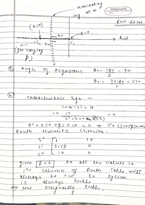
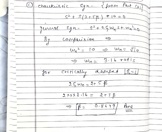
 Problem 2 For the unity feedback system below in Figure 2 G(s) Figure 2. With (8+2) G(s) = (a) Sketch the root locus. 1. Draw the finite open-loop poles and zeros. ii. Draw the real-axis root locus iii. Draw the asymptotes and root locus branches. (b) Find the value of gain that will make the system marginally stable. (c) Find the value of gain for which the closed-loop transfer function will have a pole on the real axis at s...
Question# 1 (25 points) For a unity feedback system with open loop transfer function K(s+10)(s+20) (s+30)(s2-20s+2...
 Question# 1 (25 points) For a unity feedback system with open loop transfer function K(s+10)(s+20) (s+30)(s2-20s+200) G(s) = Do the following using Matlab: a) Sketch the root locus. b) Find the range of gain, K that makes the system stable c) Find the value of K that yields a damping ratio of 0.707 for the system's closed-loop dominant poles. d) Obtain Ts, Tp, %OS for the closed loop system in part c). e) Find the value of K that yields...
3. Given the unity feedback system, where G(s) = s(s +2) (s+3)(s +4) do the following:...
 3. Given the unity feedback system, where G(s) = s(s +2) (s+3)(s +4) do the following: (a) Sketch the root locus (b) Find the asymptotes c) Find the value of gain that will make the system marginally stable (d) Find the value of gain for which the closed-loop transfer function will have a pole on the real axis at-0.5
Consider the unity feedback system is given below R(S) C(s) G(s) with transfer function: G() =...
 Consider the unity feedback system is given below R(S) C(s) G(s) with transfer function: G() = K(+2) s(s+ 1/s + 3)(+5) a) Sketch the root locus. Clearly indicate any asymptotes. b) Find the value of the gain K, that will make the system marginally stable. c) Find the value of the gain K, for which the closed-loop transfer function will have a pole on the real axis at (-0.5).
Feedback Control of Dynamic System Please Let me know how to solve this problem (5) For the following unity-feedback control system, Y(s) R(s)E D(s) (s+ 2) we want to design a controller D(s) D(s)+a)...
 Feedback Control of Dynamic System
Please Let me know how to solve this problem
(5) For the following unity-feedback control system, Y(s) R(s)E D(s) (s+ 2) we want to design a controller D(s) D(s)+a) that makes the closed-loop stable for certain positive K values. Design the parameters a and b to satisfy the design condition through the root- locus method
(5) For the following unity-feedback control system, Y(s) R(s)E D(s) (s+ 2) we want to design a controller D(s) D(s)+a)...
Feedback Control of Dynamic System
Please Let me know how to solve this problem
(5) For the following unity-feedback control system, Y(s) R(s)E D(s) (s+ 2) we want to design a controller D(s) D(s)+a) that makes the closed-loop stable for certain positive K values. Design the parameters a and b to satisfy the design condition through the root- locus method
(5) For the following unity-feedback control system, Y(s) R(s)E D(s) (s+ 2) we want to design a controller D(s) D(s)+a)...
[7] Sketch the root locus for the unity feedback system whose open loop transfer function is K G(s) Draw the root lo...
 [7] Sketch the root locus for the unity feedback system whose open loop transfer function is K G(s) Draw the root locus of the system with the gain Kas a variable. s(s+4) (s2+4s+20) Determine asymptotes, centroid, breakaway point, angle of departure, and the gain at which root locus crosses ja-axis. A control system with type-0 process and a PID controller is shown below. Design the [8 parameters of the PID controller so that the following specifications are satisfied. =100 a)...
Consider the following control system: R + Let G(s) s +23-3 and H(s) K where K is some positive c...
 Consider the following control system: R + Let G(s) s +23-3 and H(s) K where K is some positive constant. The transfer function H(s) can be considered a proportional feedback controller. (a) Examine the behavior of the system for different values of K. Try the values K 2, 4, 8. In each case, plot the pole-zero map of the closed-loop system and examine the step response. Comment on the stability of the system. Find the value of K for which...
Consider the following unity feedback system for Problems 2-3 R(9) —tqKAG YIS) Figure 1 Problem 2...
 Consider the following unity feedback system for Problems 2-3 R(9) —tqKAG YIS) Figure 1 Problem 2 Consider the system shown in the above figure, where G(s) = s(8+1128+1) a) Draw a Bode diagram of the open-loop transfer function G(s) when K=1. b) On your plot, indicate the crossover frequencies, PM, and GM. Is the closed-loop system stable with K=1? c) Determine the range of K for which the closed-loop systems will be stable. d) Verify your answer in (c) using...
A second-order process is described by its transfer function G(s) = (s+1)(843) and a PI controlle...
 A second-order process is described by its transfer function G(s) = (s+1)(843) and a PI controller by Consider feedback control with unit feedback gain as shown in Figure 1 A disturbance D(s) exists, and to achieve zero steady-state error, a small integral component is applied. Technical limitations restrict the controller gain kp to values of 0.2 or less. The goal is to examine the influence of the controller parameter k on the dynamic response. D(s) Controller Process X(s) Y(s) Figure...
1. Consider the following feedback control system Controller Process 1 G(s) R(s) Y(s) $2+5s+6 Below are...
 1. Consider the following feedback control system Controller Process 1 G(s) R(s) Y(s) $2+5s+6 Below are two potential controllers for this system: 1) Ge(s) K (Proportional controller) 2) Ge(s) K(1 1/s) (Proportional-integral controller) The design specifications are t 3.2s and P. 0. 10% for a unit step input (a) Determine the area on the S-plane where the dominant closed loop poles must be located such that the design requirements are satisfied. (b) Sketch the root locus with each of the...
 Problem 2 For the unity feedback system below in Figure 2 G(s) Figure 2. With (8+2) G(s) = (a) Sketch the root locus. 1. Draw the finite open-loop poles and zeros. ii. Draw the real-axis root locus iii. Draw the asymptotes and root locus branches. (b) Find the value of gain that will make the system marginally stable. (c) Find the value of gain for which the closed-loop transfer function will have a pole on the real axis at s...
 Question# 1 (25 points) For a unity feedback system with open loop transfer function K(s+10)(s+20) (s+30)(s2-20s+200) G(s) = Do the following using Matlab: a) Sketch the root locus. b) Find the range of gain, K that makes the system stable c) Find the value of K that yields a damping ratio of 0.707 for the system's closed-loop dominant poles. d) Obtain Ts, Tp, %OS for the closed loop system in part c). e) Find the value of K that yields...
 3. Given the unity feedback system, where G(s) = s(s +2) (s+3)(s +4) do the following: (a) Sketch the root locus (b) Find the asymptotes c) Find the value of gain that will make the system marginally stable (d) Find the value of gain for which the closed-loop transfer function will have a pole on the real axis at-0.5
 Consider the unity feedback system is given below R(S) C(s) G(s) with transfer function: G() = K(+2) s(s+ 1/s + 3)(+5) a) Sketch the root locus. Clearly indicate any asymptotes. b) Find the value of the gain K, that will make the system marginally stable. c) Find the value of the gain K, for which the closed-loop transfer function will have a pole on the real axis at (-0.5).
 Feedback Control of Dynamic System
Please Let me know how to solve this problem
(5) For the following unity-feedback control system, Y(s) R(s)E D(s) (s+ 2) we want to design a controller D(s) D(s)+a) that makes the closed-loop stable for certain positive K values. Design the parameters a and b to satisfy the design condition through the root- locus method
(5) For the following unity-feedback control system, Y(s) R(s)E D(s) (s+ 2) we want to design a controller D(s) D(s)+a)...
Feedback Control of Dynamic System
Please Let me know how to solve this problem
(5) For the following unity-feedback control system, Y(s) R(s)E D(s) (s+ 2) we want to design a controller D(s) D(s)+a) that makes the closed-loop stable for certain positive K values. Design the parameters a and b to satisfy the design condition through the root- locus method
(5) For the following unity-feedback control system, Y(s) R(s)E D(s) (s+ 2) we want to design a controller D(s) D(s)+a)...
 [7] Sketch the root locus for the unity feedback system whose open loop transfer function is K G(s) Draw the root locus of the system with the gain Kas a variable. s(s+4) (s2+4s+20) Determine asymptotes, centroid, breakaway point, angle of departure, and the gain at which root locus crosses ja-axis. A control system with type-0 process and a PID controller is shown below. Design the [8 parameters of the PID controller so that the following specifications are satisfied. =100 a)...
 Consider the following control system: R + Let G(s) s +23-3 and H(s) K where K is some positive constant. The transfer function H(s) can be considered a proportional feedback controller. (a) Examine the behavior of the system for different values of K. Try the values K 2, 4, 8. In each case, plot the pole-zero map of the closed-loop system and examine the step response. Comment on the stability of the system. Find the value of K for which...
 Consider the following unity feedback system for Problems 2-3 R(9) —tqKAG YIS) Figure 1 Problem 2 Consider the system shown in the above figure, where G(s) = s(8+1128+1) a) Draw a Bode diagram of the open-loop transfer function G(s) when K=1. b) On your plot, indicate the crossover frequencies, PM, and GM. Is the closed-loop system stable with K=1? c) Determine the range of K for which the closed-loop systems will be stable. d) Verify your answer in (c) using...
 A second-order process is described by its transfer function G(s) = (s+1)(843) and a PI controller by Consider feedback control with unit feedback gain as shown in Figure 1 A disturbance D(s) exists, and to achieve zero steady-state error, a small integral component is applied. Technical limitations restrict the controller gain kp to values of 0.2 or less. The goal is to examine the influence of the controller parameter k on the dynamic response. D(s) Controller Process X(s) Y(s) Figure...
 1. Consider the following feedback control system Controller Process 1 G(s) R(s) Y(s) $2+5s+6 Below are two potential controllers for this system: 1) Ge(s) K (Proportional controller) 2) Ge(s) K(1 1/s) (Proportional-integral controller) The design specifications are t 3.2s and P. 0. 10% for a unit step input (a) Determine the area on the S-plane where the dominant closed loop poles must be located such that the design requirements are satisfied. (b) Sketch the root locus with each of the...
Most questions answered within 3 hours.
-
Write a program to solve the Josephus problem, with the following
modification:
Sample Input:
./a.out n...
asked 52 minutes ago -
At the start of a CD it is spinning at a rate of 525 rpm
(revolutions...
asked 1 hour ago -
4. Without doing any calculations, predict whether the observed
∆T would increase, decrease or remain the...
asked 2 hours ago -
Based on the range, which of the following sets of scores has
the greatest variability? 3,...
asked 3 hours ago -
Ripples in a pond travel at a velocity of 3 m/s with one peak
passing a...
asked 3 hours ago -
A man stands on the roof of a building of height 13.0 mm and
throws a...
asked 3 hours ago -
The extent to which assets are financed by borrowed funds and
other liabilities is indicated by:...
asked 4 hours ago -
Explain in detail
Germany is the fifth largest economy
explain what goods and services Germany specializes...
asked 5 hours ago -
The density of platinum is 21.45 g/mL. If a cube of platinum
with a mass of...
asked 5 hours ago -
Accounts Receivable
Sales
A/R Posting
Extended Sales Invoice
Packing Slip
Compare invoice to packing slip 2...
asked 5 hours ago -
Michaella, age 23, is a full-time law student and is claimed by
her parents as a...
asked 5 hours ago -
Why are polymers not typically casted into products?
asked 5 hours ago