Question
find application in colour television, missile tracking and space telemetry. The filter for a particular application is chosen as: 10(s +10) (s +D(s +100) F(s) It is desired to minimize the steady state error of the system for a ramp change in the phase information signal. (a) Determine the value of the gain Kg-K in order to maintain a stable system. (b) It is decided that a steady state error equal to 1° is acceptable for a ramp signal of 100 rad/s. For that value of gain K , determine the location of the rools of the system. [Dorfl)
Homework Answers
Answer #1

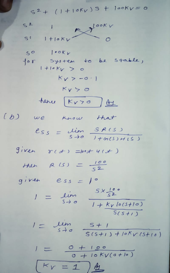
1*/s F IS) Sat (a + than kv, Fhs S+
o Systen to be stable , kv-o Cb we now hat S 2 ven ess )。 g ' SestI
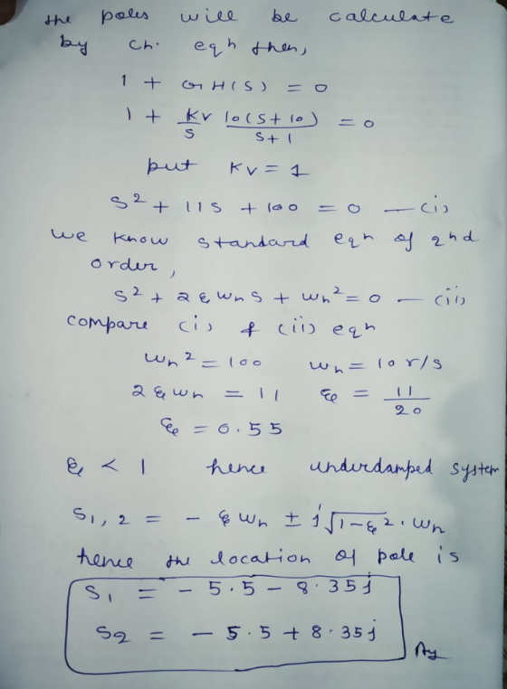
St CI we know standard eh o rdur C1 1) comparu ci ci eh 2 0 5.5-9.35 ら9.
Know the answer?
Add Answer to:
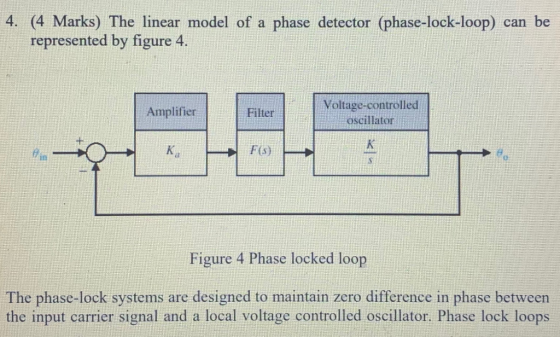
4. (4 Marks) The linear model of a phase detector (phase-lock-loop) can be represented by figure 4. Voltage-controlled oscillator Amplifier Filter LE Figure 4 Phase locked loop The phase-lock systems...
Not the answer you're looking for?
Ask your own homework help question.
Our experts will answer your question WITHIN MINUTES for Free.
Similar Homework Help Questions
Bode Diagram 10 10 Frequency (rad/s) Bode Diagram 100F 140 10 10 Frequency (rad/s) Figure Q4.2 4. The de servo system s...
 Bode Diagram 10 10 Frequency (rad/s) Bode Diagram 100F 140 10 10 Frequency (rad/s) Figure Q4.2 4. The de servo system shown in Figure Q4.1 is required to have a transient step response speci fication with a peak time of 0.58 seconds or better, and a +2% setting time of 1.7 seconds or better 01(s) K (s)G(s) s(s 1 (s 5) Figure Q4.1 The Bode diagram of the open-loop system is shown in Figure Q4.2 on page 8. This Bode...
 Bode Diagram 10 10 Frequency (rad/s) Bode Diagram 100F 140 10 10 Frequency (rad/s) Figure Q4.2 4. The de servo system shown in Figure Q4.1 is required to have a transient step response speci fication with a peak time of 0.58 seconds or better, and a +2% setting time of 1.7 seconds or better 01(s) K (s)G(s) s(s 1 (s 5) Figure Q4.1 The Bode diagram of the open-loop system is shown in Figure Q4.2 on page 8. This Bode...
ADVERTISEMENT
Need Online Homework Help?
Ask
a QuestionGet Answers For Free
Most questions answered within 3 hours.
Most questions answered within 3 hours.
ADVERTISEMENT
ADVERTISEMENT
Active Questions
-
Calculate the pH of each of the following solutions.
0.50 M HBr
3.1×10⁻⁴ M KOH
4.2×10⁻⁵...
asked 57 minutes ago -
For the year ended December 31, Depot Max’s cost of merchandise
sold was $85,600. Inventory at the...
asked 57 minutes ago -
Week 10 - Professional Memo Assignment
Professional Memo Assignment
Your mission for this week, should you...
asked 1 hour ago -
Write a Python program that stores the data for each
player on the team, and it...
asked 1 hour ago -
In
the last 3 months, mike never knows when he is going to get his
allowance...
asked 1 hour ago -
Is Ca(OH)2 a Bronsted base, Lewis base, or both? Why?
asked 1 hour ago -
1A- Why don’t voters complain about U.S. tariffs on imported
sugar?
Because sugar is only a...
asked 1 hour ago -
Cash Payback Period
Primera Banco is evaluating two capital investment proposals for
a drive-up ATM kiosk,...
asked 1 hour ago -
Create a button in Swift (Xcode) that will create a charge,
create a charge using Stripe's...
asked 1 hour ago -
The reaction rate of CO and NO2 in the reaction
CO(g) + NO2(g) → CO2(g) +...
asked 1 hour ago -
Imagine that a chemist puts 6.40 mol each of
C3H8 and O2 in a 1.00-L container...
asked 1 hour ago -
How much money should be invested today in order to have $8340
at the end of...
asked 1 hour ago
ADVERTISEMENT