
Homework Answers
Matlab code is given below in bold letters.
clc;
close all;
clear all;
% define the lapalce variable s
s = tf('s');
% define the plant
Gp = 1/(s^2+5*s+6);
% plot the root locus with proportional controller
% define gain k
k = 0:0.1:100;
figure;rlocus(Gp,k);
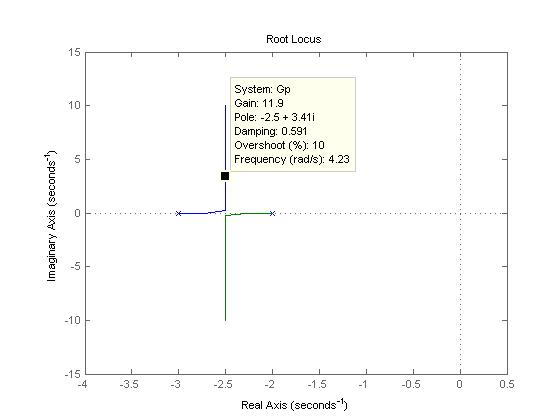
From the above figure, it is observed that the %overshoot is 10 % for a gain of 11.9.
Time constant = 1/2.5 = 0.4 sec
Therefore the settling time = 4*T = 4*0.4 = 1.6 sec.
% Question 2 integral controller
% MATLAB code is in bold letter
% plot the root lcous with integral controller alone
% define gain k
k = 0:0.1:100;
figure;rlocus(Gp/s,k);

From the above figure, it is observed that the %overshoot is 10 % for a gain of 4.4.
Time constant = 1/0.65 = 1.5385 sec
Therefore the settling time = 4*T = 4*1.5385 = 6.1538 sec.
% Question 3 Proportional + integral controller
% plot the root lcous with proportional integral controller
% define gain k
k = 0:0.1:100;
figure;rlocus(Gp*(s+1)/s,k);
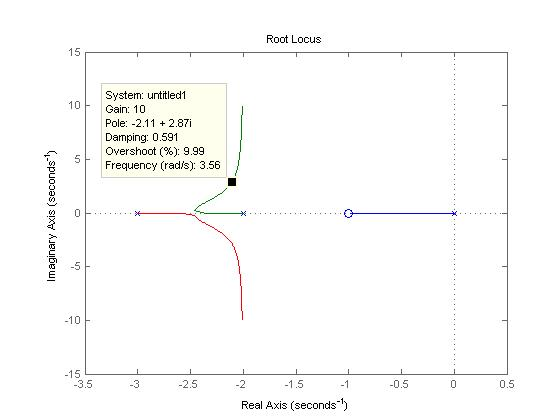
From the above figure, it is observed that the % overshoot is 10 % for a gain of 10.
Time constant = 1/2.11= 0.4739sec
Therefore the settling time = 4*T = 4*0.4739 = 1.8957sec.
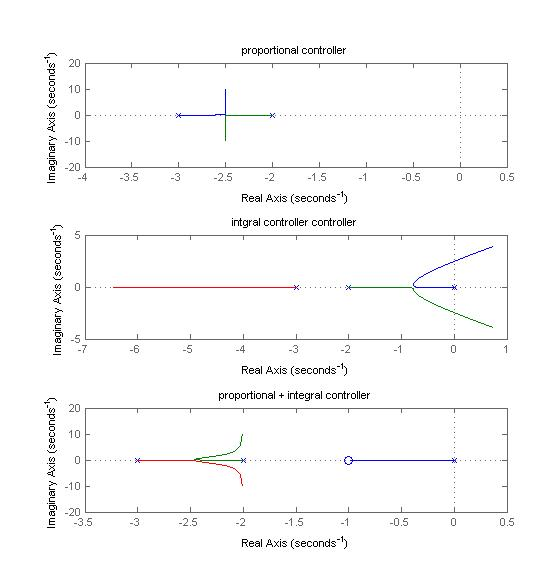
% Question d
figure;
subplot(311);
rlocus(Gp,k);
title('proportional controller');
subplot(312);
rlocus(Gp/s,k);
title('intgral controller controller');
subplot(313);
rlocus(Gp*(s+1)/s,k);
title('proportional + integral controller');
Add Answer to:
PROBLEM 4 Suppose that a system is shown in Figure 4. There are three controllers that might be incorporated into this system. 1. Ge (s)-K (proportional (P) controller) 2. GS)K/s (integral (I) contro...
Please wriite the matlab code of the question
 &&&&&&&&&&&&&&&&&&&&&&&&&&&&&&&
Please wriite the matlab code of the question :)))
&&&&&&&&&&&&&&&&&&&&&&&&&&&&&&&
PROBLEM 4 Suppose that a system is shown in Figure 4. There are three controllers that might be incorporated into this system. 1·G,(s)-K (proportional (P) controller) 2·G,(s)=K/s (integral (I) controller) 3. G (s) K(1+1/s) (proportional, integral (PI) controller) The system requirements are Ts < 10 seconds and P.。. 10% for a unit step response. (a) For the (P) controller, write a piece of MATLAB code to plot root locus...
&&&&&&&&&&&&&&&&&&&&&&&&&&&&&&&
Please wriite the matlab code of the question :)))
&&&&&&&&&&&&&&&&&&&&&&&&&&&&&&&
PROBLEM 4 Suppose that a system is shown in Figure 4. There are three controllers that might be incorporated into this system. 1·G,(s)-K (proportional (P) controller) 2·G,(s)=K/s (integral (I) controller) 3. G (s) K(1+1/s) (proportional, integral (PI) controller) The system requirements are Ts < 10 seconds and P.。. 10% for a unit step response. (a) For the (P) controller, write a piece of MATLAB code to plot root locus...
PROBLEM 4 A unity feedback closed loop control system is displayed in Figure 4 (a) Assume that the controller is given by G (s)-2. Based on the lsim function of MATLAB, calculate and obtain the g...
 PROBLEM 4 A unity feedback closed loop control system is displayed in Figure 4 (a) Assume that the controller is given by G (s)-2. Based on the lsim function of MATLAB, calculate and obtain the graph of the response for 0,(1)-a. Here a ; 0.5%, Find the height error after 10 seconds, (b) In order to reduce the steady-state error, substitute G. (s) with the following controller: K2 This is a Proportional-Integral (PI) controller. Repeat part (a) in the presence...
1. Consider the following feedback control system Controller Process 1 G(s) R(s) Y(s) $2+5s+6 Below are...
 1. Consider the following feedback control system Controller Process 1 G(s) R(s) Y(s) $2+5s+6 Below are two potential controllers for this system: 1) Ge(s) K (Proportional controller) 2) Ge(s) K(1 1/s) (Proportional-integral controller) The design specifications are t 3.2s and P. 0. 10% for a unit step input (a) Determine the area on the S-plane where the dominant closed loop poles must be located such that the design requirements are satisfied. (b) Sketch the root locus with each of the...
A unity feedback closed loop control system is displayed in Figure 4. (a) Assume that the control...
 Please solve as a MATLAB code.
A unity feedback closed loop control system is displayed in Figure 4. (a) Assume that the controller is given by G (s) 2. Based on the lsim function of MATLAB, calculate and obtain the graph of the response for (t) at. Here a 0.5°/s. Find the height error after 10 seconds, (b) In order to reduce the steady-state error, substitute G (s) with the following controller This is a Proportional-Integral (PI) controller. Repeat part...
Please solve as a MATLAB code.
A unity feedback closed loop control system is displayed in Figure 4. (a) Assume that the controller is given by G (s) 2. Based on the lsim function of MATLAB, calculate and obtain the graph of the response for (t) at. Here a 0.5°/s. Find the height error after 10 seconds, (b) In order to reduce the steady-state error, substitute G (s) with the following controller This is a Proportional-Integral (PI) controller. Repeat part...
Consider a unity-feedback control system with a PI controller Gpr(s) and a plant G(s) in cascade. In particular, the plant transfer function is given as 2. G(s) = s+4, and the PI controller trans...
 Consider a unity-feedback control system with a PI controller Gpr(s) and a plant G(s) in cascade. In particular, the plant transfer function is given as 2. G(s) = s+4, and the PI controller transfer function is of the forrm KI p and Ki are the proportional and integral controller gains, respectively where K Design numerical values for Kp and Ki such that the closed-loop control system has a step- response settling time T, 0.5 seconds with a damping ratio of...
1. A feedback control system is shown in the figure below. Suppose that our design objective...
 1. A feedback control system is shown in the figure below. Suppose that our design objective is to find a controller Gc(S) of minimal complexity such that our closed-loop system can track a unit step input with a steady-state error of zero. (b) Now consider a more complex controller Gc(S) = [ Ko + K//s] where Ko = 2 and Ki = 20. (This is a proportional + integral (PI) controller). Plot the unit step response, and determine the steady-state...
If the integral term K is zero, the corresponding controller is known as a proportional-derivativ...
 If the integral term K is zero, the corresponding controller is known as a proportional-derivative (or PD) controller. By setting K0 and equating coefficients, show that the two PD controllers above have equivalence to the mechanical systems to the mechanical systems shown in Figure 1 and from this make interpretations of the functions of the P and D terms of a PID controller. x(t) yCt) (a) Damper in the forward path xCt) yCt) M ㄧㄧㄒㄧ- m (b) Damper in the...
Problem 2. (40 points) The following figure shows the block diagram of a feedback closed loop...
 Problem 2. (40 points) The following figure shows the block diagram of a feedback closed loop control system. Ysp(s) - Es) | U(s) Y(s) S +5 1 Ge(s) Q"46:0) " ** 52_1 (a) Find the range of controller settings that yield stable closed-loop system for: (i) A proportional-only (P) controller. (ii) A proportional-integral (PI) controller. (b) For the PI control, modify the block diagram to eliminate proportional kick.
4 k(s+2) For the system (s) = design a controller in the form of K(s) =...
 4 k(s+2) For the system (s) = design a controller in the form of K(s) = s(s+4) (s+p) Such that the closed loop step response has the following specifications: 4 TS = — sec 3 T = sec P 4 Where T, is the settling time and T, is the peak time. Hint: Use the given requirements to find the place of desired poles
R(s) Q1 (25p). The closed loop control system is shown in the figure. The response of...
 R(s) Q1 (25p). The closed loop control system is shown in the figure. The response of the control system to a unit step reference input is shown in below. C(s) Kp 0.6 S2 + 5s + A 4 a) Find and wn. b) Find Ke and A c) If we use a proportional-integral (PI) controller instead of a proportional (P) controller, how the graph would be expected to change. For two different integral coefficients (bigger Ki_1 and smaller K_2), make...
 &&&&&&&&&&&&&&&&&&&&&&&&&&&&&&&
Please wriite the matlab code of the question :)))
&&&&&&&&&&&&&&&&&&&&&&&&&&&&&&&
PROBLEM 4 Suppose that a system is shown in Figure 4. There are three controllers that might be incorporated into this system. 1·G,(s)-K (proportional (P) controller) 2·G,(s)=K/s (integral (I) controller) 3. G (s) K(1+1/s) (proportional, integral (PI) controller) The system requirements are Ts < 10 seconds and P.。. 10% for a unit step response. (a) For the (P) controller, write a piece of MATLAB code to plot root locus...
&&&&&&&&&&&&&&&&&&&&&&&&&&&&&&&
Please wriite the matlab code of the question :)))
&&&&&&&&&&&&&&&&&&&&&&&&&&&&&&&
PROBLEM 4 Suppose that a system is shown in Figure 4. There are three controllers that might be incorporated into this system. 1·G,(s)-K (proportional (P) controller) 2·G,(s)=K/s (integral (I) controller) 3. G (s) K(1+1/s) (proportional, integral (PI) controller) The system requirements are Ts < 10 seconds and P.。. 10% for a unit step response. (a) For the (P) controller, write a piece of MATLAB code to plot root locus...
 PROBLEM 4 A unity feedback closed loop control system is displayed in Figure 4 (a) Assume that the controller is given by G (s)-2. Based on the lsim function of MATLAB, calculate and obtain the graph of the response for 0,(1)-a. Here a ; 0.5%, Find the height error after 10 seconds, (b) In order to reduce the steady-state error, substitute G. (s) with the following controller: K2 This is a Proportional-Integral (PI) controller. Repeat part (a) in the presence...
 1. Consider the following feedback control system Controller Process 1 G(s) R(s) Y(s) $2+5s+6 Below are two potential controllers for this system: 1) Ge(s) K (Proportional controller) 2) Ge(s) K(1 1/s) (Proportional-integral controller) The design specifications are t 3.2s and P. 0. 10% for a unit step input (a) Determine the area on the S-plane where the dominant closed loop poles must be located such that the design requirements are satisfied. (b) Sketch the root locus with each of the...
 Please solve as a MATLAB code.
A unity feedback closed loop control system is displayed in Figure 4. (a) Assume that the controller is given by G (s) 2. Based on the lsim function of MATLAB, calculate and obtain the graph of the response for (t) at. Here a 0.5°/s. Find the height error after 10 seconds, (b) In order to reduce the steady-state error, substitute G (s) with the following controller This is a Proportional-Integral (PI) controller. Repeat part...
Please solve as a MATLAB code.
A unity feedback closed loop control system is displayed in Figure 4. (a) Assume that the controller is given by G (s) 2. Based on the lsim function of MATLAB, calculate and obtain the graph of the response for (t) at. Here a 0.5°/s. Find the height error after 10 seconds, (b) In order to reduce the steady-state error, substitute G (s) with the following controller This is a Proportional-Integral (PI) controller. Repeat part...
 Consider a unity-feedback control system with a PI controller Gpr(s) and a plant G(s) in cascade. In particular, the plant transfer function is given as 2. G(s) = s+4, and the PI controller transfer function is of the forrm KI p and Ki are the proportional and integral controller gains, respectively where K Design numerical values for Kp and Ki such that the closed-loop control system has a step- response settling time T, 0.5 seconds with a damping ratio of...
 1. A feedback control system is shown in the figure below. Suppose that our design objective is to find a controller Gc(S) of minimal complexity such that our closed-loop system can track a unit step input with a steady-state error of zero. (b) Now consider a more complex controller Gc(S) = [ Ko + K//s] where Ko = 2 and Ki = 20. (This is a proportional + integral (PI) controller). Plot the unit step response, and determine the steady-state...
 If the integral term K is zero, the corresponding controller is known as a proportional-derivative (or PD) controller. By setting K0 and equating coefficients, show that the two PD controllers above have equivalence to the mechanical systems to the mechanical systems shown in Figure 1 and from this make interpretations of the functions of the P and D terms of a PID controller. x(t) yCt) (a) Damper in the forward path xCt) yCt) M ㄧㄧㄒㄧ- m (b) Damper in the...
 Problem 2. (40 points) The following figure shows the block diagram of a feedback closed loop control system. Ysp(s) - Es) | U(s) Y(s) S +5 1 Ge(s) Q"46:0) " ** 52_1 (a) Find the range of controller settings that yield stable closed-loop system for: (i) A proportional-only (P) controller. (ii) A proportional-integral (PI) controller. (b) For the PI control, modify the block diagram to eliminate proportional kick.
 4 k(s+2) For the system (s) = design a controller in the form of K(s) = s(s+4) (s+p) Such that the closed loop step response has the following specifications: 4 TS = — sec 3 T = sec P 4 Where T, is the settling time and T, is the peak time. Hint: Use the given requirements to find the place of desired poles
 R(s) Q1 (25p). The closed loop control system is shown in the figure. The response of the control system to a unit step reference input is shown in below. C(s) Kp 0.6 S2 + 5s + A 4 a) Find and wn. b) Find Ke and A c) If we use a proportional-integral (PI) controller instead of a proportional (P) controller, how the graph would be expected to change. For two different integral coefficients (bigger Ki_1 and smaller K_2), make...
Most questions answered within 3 hours.
-
A solid, uniform disk of radius 0.250 m and mass 53.7 kg rolls
down a ramp...
asked 2 hours ago -
Given the following table of high speed internet access vs.
annual home income:
Home Income
%...
asked 2 hours ago -
A baseball batter hits a 0.145kg baseball straight up into the
air. The baseball leaves the...
asked 2 hours ago -
An FM modulator is tested using
single-tone baseband signal with frequency of 50kHz and a sprectrum...
asked 3 hours ago -
Write the ionic equations for the first stage of salts
hydrolysis.
Anion, Cation?
Na2S
NiSO4
K2SO4...
asked 4 hours ago -
suppose there is a normally distributed population with a mean of
250 and a standard deviation...
asked 5 hours ago -
Question Three
Suppose you as project manager are using the Waterfall
development methodology on a large...
asked 6 hours ago -
Which statement is not true about welfare in Canada?
A.Benefits typically vary based on one's ability...
asked 7 hours ago -
Please help me with FLOWCHART and UML diagram for class,
thank you!
#include <iostream>
#include <fstream>...
asked 7 hours ago -
3. Describe the “logic circuit” of the Lac operon. Which
proteins are bound or not to...
asked 7 hours ago -
Ayesha’s adjusted gross income is $60,000 in 2019. She donated a
piece of artwork with a...
asked 7 hours ago -
For Dijkstra’s shortest path algorithm:
a. Give the Big-O time for Dijkstra’s shortest path algorithm
and...
asked 8 hours ago