

120 kips 120 kips Figure P-1
Homework Answers


 I
hope I could help u
I
hope I could help u
Add Answer to:
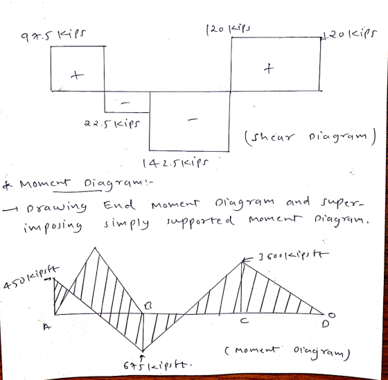
1-(25%) Draw shear and moment diagrams for the beam shown in Figure P-1 . Draw a sketch of the deflected shape. The spans are 30-ft long each (total of 90-ft), the concentrated loads are eac...
1 Draw the shear-moment diagrams for the simple beam with the two concentrated loads as shown...
 1 Draw the shear-moment diagrams for the simple beam with the two concentrated loads as shown in the figure below. 12 ft 8 ft Fe=20 kips Fc=15 kips
Draw/ influence lines for shear to the left of A, shear at B, and moment at C.
 1-(25%) Draw shear and moment diagrams for the beam shown in Figure P-1. Draw a sketch of the deflected shape 2-(25%) Using moment area method, for the beam shown in Figure P-2 find deflection at A. Also, determine the location and value of the maximum deflection in span BC. El is constant 3-(25%) For the frame shown in Figure P-3-find member frees and draw shear and moment diagrams. 4-(25%) Draw/ influence lines for shear to the left of A, shear at B, and...
For beam given below Draw the shear- and moment diagrams. Label all important values of shear...
 For beam given below Draw the shear- and moment diagrams. Label all important values of shear and moment. nclude the conventions for shear and moment directly on the diagrams Sketch the deflected shape To reeiv leredr you mus ue astraighto sbwg ns 3 kips 12 kip-ft 4 ft 4 ft 4 ft
Draw the Shear & Moment Diagrams and sketch the deflected shape for the beams shown below...
 Draw the Shear & Moment Diagrams and sketch the deflected shape for the beams shown below (Indicate values at points of change and minimums and maximums. Also indicate units near values or on each drawing axis) Scan or photograph when completed. Submit on Moodle as a .pdf or .jpg 10k w = 200 lb/ft 2k W = 800 lb/ft 10 ft 5 ft 5ft > 10 ft ** 5+ > 5 > M M D D
Problem 5 Three moment equation. Analyze and draw the bending moment and shear force diagrams for...
 Problem 5 Three moment equation. Analyze and draw the bending moment and shear force diagrams for the following multi-span beam (typical for a roof beam of a building): Number of spans: Length of interior spans: Length of exterior spans: 0.8L Flexural stiffness Loading Supports: 4 El (same for all spans) W (uniformly-distributed load on all spans) Left support is a pin, all others are rollers.
Construct the shear and bending moment diagrams and the qualitative deflected shape for each of the...
 Construct the shear and bending moment diagrams and the
qualitative deflected shape for each of the beams
shown.
5.45) 20 kips 2 kips/ft Hing 10' 10' 30
Construct the shear and bending moment diagrams and the
qualitative deflected shape for each of the beams
shown.
5.45) 20 kips 2 kips/ft Hing 10' 10' 30
Draw the shear and bending moment diagrams and the qualitative deflected shape for the beam shown in Fig. 5.10(a)
 Draw the shear and bending moment diagrams and the qualitative deflected shape for the beam shown in Fig. 5.10(a)
a Determine the reactions b) Draw the shear and moment diagrams c) Sketch the deflected shape
 a Determine the reactions b) Draw the shear and moment diagrams c) Sketch the deflected shape
Analyze the Frames shown below. Draw the shear and moment diagrams and sketch the approximate deflected...
 Analyze the Frames shown below. Draw the shear and moment
diagrams and sketch the approximate deflected shape
Settlement at A = 1” and at C = .5” E = 30000 kis, I = 240
in4
2k/ft 8 k B EI EI 36 k-ft С 12'1 EI A 12' 8'
Analyze the Frames shown below. Draw the shear and moment
diagrams and sketch the approximate deflected shape
Settlement at A = 1” and at C = .5” E = 30000 kis, I = 240
in4
2k/ft 8 k B EI EI 36 k-ft С 12'1 EI A 12' 8'
A) The internal span CD on a continuous beam is deflected as shown (Figure 2) as...
 A) The internal span CD on a continuous beam is deflected as
shown (Figure 2) as a result of loads on other portions of the
beam, where L = 25 ft , α = 0.75 ∘, β = 0.35 ∘, E =
2.9×10⁴ ksi , and I = 1500 in4 . There is no vertical
deflection at either end. What is the internal moment at D?
M_D
B)The end span EF on a continuous beam is deflected as shown
(Figure...
A) The internal span CD on a continuous beam is deflected as
shown (Figure 2) as a result of loads on other portions of the
beam, where L = 25 ft , α = 0.75 ∘, β = 0.35 ∘, E =
2.9×10⁴ ksi , and I = 1500 in4 . There is no vertical
deflection at either end. What is the internal moment at D?
M_D
B)The end span EF on a continuous beam is deflected as shown
(Figure...
 1 Draw the shear-moment diagrams for the simple beam with the two concentrated loads as shown in the figure below. 12 ft 8 ft Fe=20 kips Fc=15 kips
 For beam given below Draw the shear- and moment diagrams. Label all important values of shear and moment. nclude the conventions for shear and moment directly on the diagrams Sketch the deflected shape To reeiv leredr you mus ue astraighto sbwg ns 3 kips 12 kip-ft 4 ft 4 ft 4 ft
 Draw the Shear & Moment Diagrams and sketch the deflected shape for the beams shown below (Indicate values at points of change and minimums and maximums. Also indicate units near values or on each drawing axis) Scan or photograph when completed. Submit on Moodle as a .pdf or .jpg 10k w = 200 lb/ft 2k W = 800 lb/ft 10 ft 5 ft 5ft > 10 ft ** 5+ > 5 > M M D D
 Problem 5 Three moment equation. Analyze and draw the bending moment and shear force diagrams for the following multi-span beam (typical for a roof beam of a building): Number of spans: Length of interior spans: Length of exterior spans: 0.8L Flexural stiffness Loading Supports: 4 El (same for all spans) W (uniformly-distributed load on all spans) Left support is a pin, all others are rollers.
 Construct the shear and bending moment diagrams and the
qualitative deflected shape for each of the beams
shown.
5.45) 20 kips 2 kips/ft Hing 10' 10' 30
Construct the shear and bending moment diagrams and the
qualitative deflected shape for each of the beams
shown.
5.45) 20 kips 2 kips/ft Hing 10' 10' 30
 a Determine the reactions b) Draw the shear and moment diagrams c) Sketch the deflected shape
 Analyze the Frames shown below. Draw the shear and moment
diagrams and sketch the approximate deflected shape
Settlement at A = 1” and at C = .5” E = 30000 kis, I = 240
in4
2k/ft 8 k B EI EI 36 k-ft С 12'1 EI A 12' 8'
Analyze the Frames shown below. Draw the shear and moment
diagrams and sketch the approximate deflected shape
Settlement at A = 1” and at C = .5” E = 30000 kis, I = 240
in4
2k/ft 8 k B EI EI 36 k-ft С 12'1 EI A 12' 8'
 A) The internal span CD on a continuous beam is deflected as
shown (Figure 2) as a result of loads on other portions of the
beam, where L = 25 ft , α = 0.75 ∘, β = 0.35 ∘, E =
2.9×10⁴ ksi , and I = 1500 in4 . There is no vertical
deflection at either end. What is the internal moment at D?
M_D
B)The end span EF on a continuous beam is deflected as shown
(Figure...
A) The internal span CD on a continuous beam is deflected as
shown (Figure 2) as a result of loads on other portions of the
beam, where L = 25 ft , α = 0.75 ∘, β = 0.35 ∘, E =
2.9×10⁴ ksi , and I = 1500 in4 . There is no vertical
deflection at either end. What is the internal moment at D?
M_D
B)The end span EF on a continuous beam is deflected as shown
(Figure...
Most questions answered within 3 hours.
-
3) What are the typical social structures in a global city?
asked 2 hours ago -
Luther Corporation
Consolidated Balance Sheet
December 31, 2019 and 2018 (in $ millions)
Assets
2019
2018...
asked 2 hours ago -
(Expected rate of return and risk) Carter Inc. is evaluating a
security. Calculate the investment’s expected...
asked 4 hours ago -
What specific indicators can point to lack of progress for
African Americans in American society?
asked 5 hours ago -
1-The Electrons in a beam are moving at 2.7×10⁸ m/s in an
electric field of 15000...
asked 6 hours ago -
A gas tank is a vertical cylinder. It has a radius of 1m, a
height of...
asked 6 hours ago -
Accent Software faces the following conditions. All of these
support Accent’s use of a market-penetration pricing...
asked 7 hours ago -
A mathematically inclined friend emails you the following
instructions: "Meet me in the cafeteria the first...
asked 7 hours ago -
A monopoly sells in two countries . The demand curves in the two
countries are p1...
asked 8 hours ago -
A .15kg rubber ball is bounced off a wall. Before hitting the
wall, the ball moves...
asked 9 hours ago -
A manufacturing company preparing to build a new plant is
considering three potential locations for it....
asked 9 hours ago -
B. If compound Y has approximately the same values of solubility
in toluene as compound X,...
asked 9 hours ago