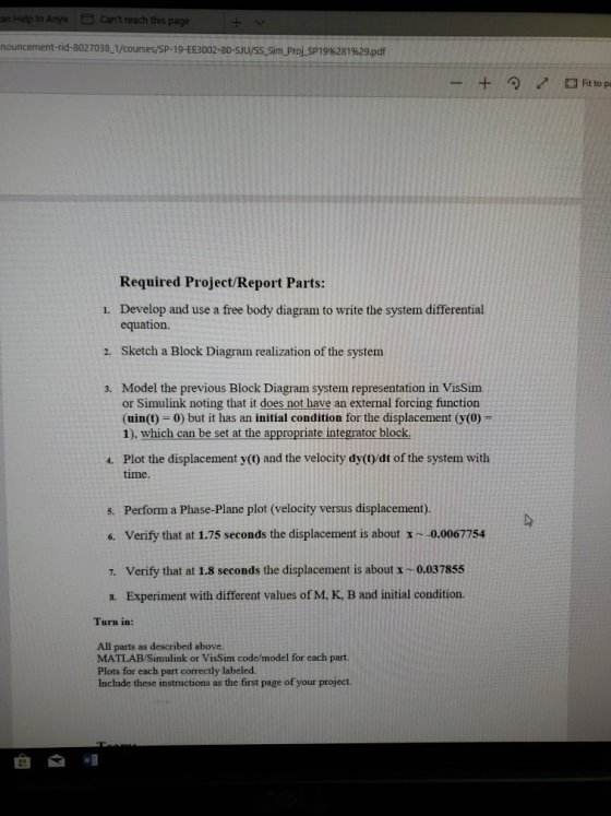
Help In Any" Can't reach this page an nouncement-rid-8027038-1/courses/SP-19-EE3002-80-SJU/SS-Sim-Proj-SP 1996281 %29pdf Required Project/Report Parts: Develop and use a free body diagram to write the system differential equation. 1. Sketch a Block Diagram realization of the system 2. 3. Model the previous Block Diagram system representation in VisSim or Simulink noting that it does not have an external forcing function (uin(t) 0) but it has an initial condition for the displacement (y(0) 1), which can be set at the appropriate integrator block 4. Plot the displacement y(t) and the velocity dy(O/dt of the system with time. Perform a Phase-Plane plot (velocity versus displacement). 5. verify that at 1.75 seconds the displacement is about x ~-0.0067754 6, 7. Verify that at 1.8 seconds the displacement is about x ~ 0.037855 Experiment with different values of M, K, B and initial condition. 8. Turn in: All parts as described above. MATLAB/Simulink or VisSim code/model for each part. Plots for each part correctly labeled. Include these instructions as the first page of your project wl 曲
Homework Answers
The SIMULINK block diagram is given below.
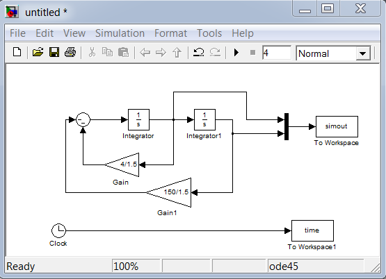
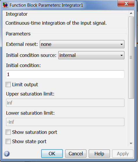
set the initial conditions as given below for integrator 1.
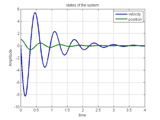
Now simulate the model and execute the following code:
figure;plot(time,simout(:,1),time,simout(:,2),'linewidth',2);grid
on;
xlabel('time');ylabel('Amplitude');title('states of the
system');legend('velocity','position');
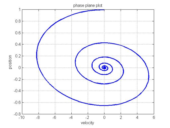
code for phase plane plot:
figure;plot(simout(:,1),simout(:,2),'linewidth',2);grid
on;
xlabel('velocity');ylabel('position');title('phase plane
plot');
Phase plane plot is plotted below
Add Answer to:
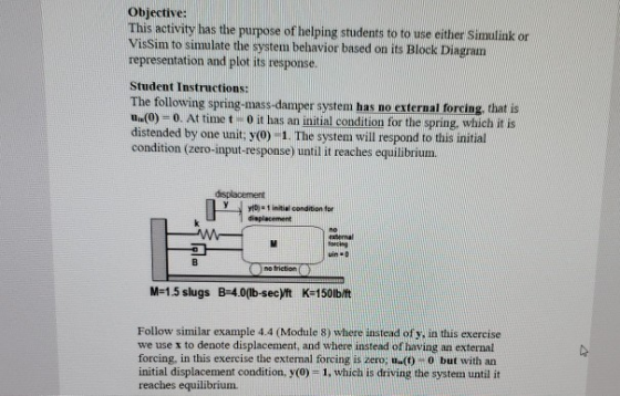
Objective: This activity has the purpose of helping students to to use either Simulink or VisSim to simulate the system behavior based on its Block Diagram representation and plot its response...
.matlab Objective: This activity has the purpose of helping students to to use either Simulink or VisSim to simulate the system behavior based on its Block Diagram representation and plot its resp...
 .matlab
Objective: This activity has the purpose of helping students to to use either Simulink or VisSim to simulate the system behavior based on its Block Diagram representation and plot its response. Student Instructions: The following spring-mass-damper system has no external forcing, that is u(0)-0. At time t- 0 it has an initial condition for the spring, which it is distended by one unit: y(0)-1. The system will respond to this initial condition (zero-input-response) until it reaches equilibrium. 0)1initial condition...
.matlab
Objective: This activity has the purpose of helping students to to use either Simulink or VisSim to simulate the system behavior based on its Block Diagram representation and plot its response. Student Instructions: The following spring-mass-damper system has no external forcing, that is u(0)-0. At time t- 0 it has an initial condition for the spring, which it is distended by one unit: y(0)-1. The system will respond to this initial condition (zero-input-response) until it reaches equilibrium. 0)1initial condition...
1) Use Simulink to plot the unit step response of the following block diagram for K-1, 2, 5 and f...
 1) Use Simulink to plot the unit step response of the following block diagram for K-1, 2, 5 and find Mp, tp, ts from the figure. (116s2 +1187s+8260) K(s) K controller plant R(s) K(s) G(s) Y(s) 2) Find the state variable representation of closed loop system of (1) by using Simulink.
1) Use Simulink to plot the unit step response of the following block diagram for K-1, 2, 5 and find Mp, tp, ts from the figure. (116s2 +1187s+8260) K(s)...
1) Use Simulink to plot the unit step response of the following block diagram for K-1, 2, 5 and find Mp, tp, ts from the figure. (116s2 +1187s+8260) K(s) K controller plant R(s) K(s) G(s) Y(s) 2) Find the state variable representation of closed loop system of (1) by using Simulink.
1) Use Simulink to plot the unit step response of the following block diagram for K-1, 2, 5 and find Mp, tp, ts from the figure. (116s2 +1187s+8260) K(s)...
Build a block diagram representation of this model in Simulink, including integration and summa...
 Build a block diagram representation of this model in Simulink,
including integration and
summation blocks.
Apply a step input to the system and plot the output y(t) for 5
seconds. Assume initial conditions for all states are 0.
Discuss the system step response: based on visual observation,
is this system stable or unstable? Based on the plot, why?
Use the Matlab command ’ss2tf’ to get a transfer function
representation for the system.
Determine the poles of the system (consider using...
Build a block diagram representation of this model in Simulink,
including integration and
summation blocks.
Apply a step input to the system and plot the output y(t) for 5
seconds. Assume initial conditions for all states are 0.
Discuss the system step response: based on visual observation,
is this system stable or unstable? Based on the plot, why?
Use the Matlab command ’ss2tf’ to get a transfer function
representation for the system.
Determine the poles of the system (consider using...
 .matlab
Objective: This activity has the purpose of helping students to to use either Simulink or VisSim to simulate the system behavior based on its Block Diagram representation and plot its response. Student Instructions: The following spring-mass-damper system has no external forcing, that is u(0)-0. At time t- 0 it has an initial condition for the spring, which it is distended by one unit: y(0)-1. The system will respond to this initial condition (zero-input-response) until it reaches equilibrium. 0)1initial condition...
.matlab
Objective: This activity has the purpose of helping students to to use either Simulink or VisSim to simulate the system behavior based on its Block Diagram representation and plot its response. Student Instructions: The following spring-mass-damper system has no external forcing, that is u(0)-0. At time t- 0 it has an initial condition for the spring, which it is distended by one unit: y(0)-1. The system will respond to this initial condition (zero-input-response) until it reaches equilibrium. 0)1initial condition...
 1) Use Simulink to plot the unit step response of the following block diagram for K-1, 2, 5 and find Mp, tp, ts from the figure. (116s2 +1187s+8260) K(s) K controller plant R(s) K(s) G(s) Y(s) 2) Find the state variable representation of closed loop system of (1) by using Simulink.
1) Use Simulink to plot the unit step response of the following block diagram for K-1, 2, 5 and find Mp, tp, ts from the figure. (116s2 +1187s+8260) K(s)...
1) Use Simulink to plot the unit step response of the following block diagram for K-1, 2, 5 and find Mp, tp, ts from the figure. (116s2 +1187s+8260) K(s) K controller plant R(s) K(s) G(s) Y(s) 2) Find the state variable representation of closed loop system of (1) by using Simulink.
1) Use Simulink to plot the unit step response of the following block diagram for K-1, 2, 5 and find Mp, tp, ts from the figure. (116s2 +1187s+8260) K(s)...
 Build a block diagram representation of this model in Simulink,
including integration and
summation blocks.
Apply a step input to the system and plot the output y(t) for 5
seconds. Assume initial conditions for all states are 0.
Discuss the system step response: based on visual observation,
is this system stable or unstable? Based on the plot, why?
Use the Matlab command ’ss2tf’ to get a transfer function
representation for the system.
Determine the poles of the system (consider using...
Build a block diagram representation of this model in Simulink,
including integration and
summation blocks.
Apply a step input to the system and plot the output y(t) for 5
seconds. Assume initial conditions for all states are 0.
Discuss the system step response: based on visual observation,
is this system stable or unstable? Based on the plot, why?
Use the Matlab command ’ss2tf’ to get a transfer function
representation for the system.
Determine the poles of the system (consider using...
Most questions answered within 3 hours.
-
1)Which of the following is an
important difference between qualified and nonqualified retirement
plans?
a. Qualified...
asked 6 minutes ago -
What's the streaming business's problem on the
horizon?
asked 1 hour ago -
I need help with writing the conclusion for this online lab
report
Abstract
By testing the...
asked 1 hour ago -
For the reaction 1N2+3H2-----> 2NH3, would the reaction rate
trend be: delta[NH3]/ delta t = -2...
asked 1 hour ago -
Within your current/past organization, identify a problem/issue
and format a design to address same. You may...
asked 1 hour ago -
A sock stuck to the side of a clothes-dryer barrel has a
centripetal acceleration of 24...
asked 2 hours ago -
A perfect gas undergoes an isentropic process such that its
volume doubles. If the ratio of...
asked 2 hours ago -
list the elements in groups 3A to 6A in the same order as in the
periodic...
asked 3 hours ago -
Estimating effect size. Peng and Chen (2014)
evaluated effect size estimates for various tests. In their...
asked 3 hours ago -
Write a script in MySQL that creates and calls a stored
procedure name test. This procedure...
asked 3 hours ago -
If we test the following: H0: μ = 17
vs. H1: μ ≠ 17 and the...
asked 3 hours ago -
in the past year TVG had revenues of 3 million, cost
of goods sold of $25...
asked 3 hours ago