
Homework Answers


Add Answer to:
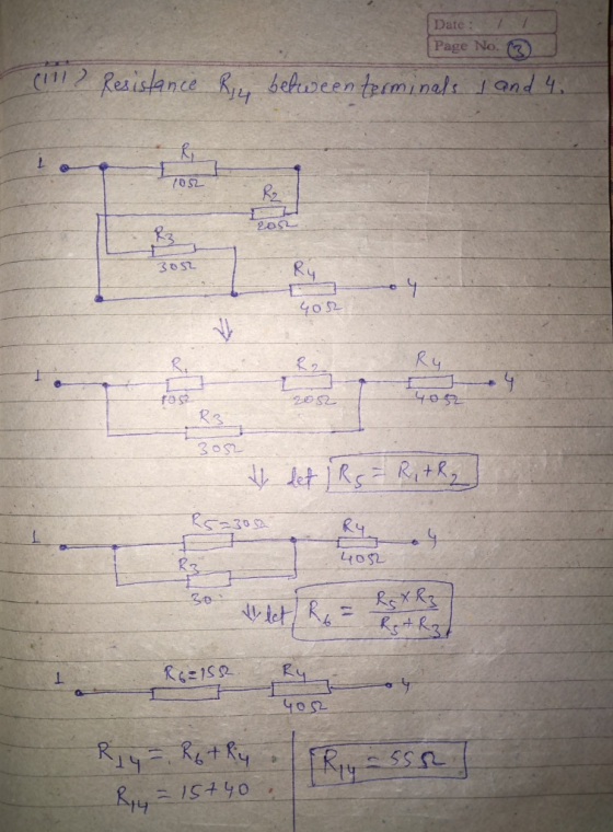
With reference to Figure Q1a, calculate the following resistances: a) i) Resistance R12 between terminals 1 and 2 i) Resistance R13 between terminals 1 and 3 Resistance R14 between terminals 1 and 4...
Calculate resistance between terminals 1 and 2, 1 and 4,1 and 3, 2 and 4, 3...
 Calculate resistance between terminals 1 and 2, 1 and 4,1 and 3, 2 and 4, 3 and 4, and 2 and 3 R1 10Ω 2 20 Ω 1 3 30 Ω | | R4 40Ω 4 Rs 50 Ω
2. For the 3 circuits below, find the equivalent resistance between nodes a and b. Figure...
 2. For the 3 circuits below, find the equivalent resistance between nodes a and b. Figure P3. 12Ω 15 | 240 120Ω 60Ω 20Ω 25Ω 7Ω 9B 10 Ω 18Ω 35 Ω 60Ω 30Ω 40Ω 5Ω 10Ω 20 Ω 14Ω 30Ω 3Ω 50 Ω 30Ω 12 Ω
The four resistors in the figure have an equivalent resistance of 16Ω. The resistances are as...
 The four resistors in the figure have an equivalent resistance
of 16Ω. The resistances are as follows: ?1=12Ω, ?2=4.0Ω, and
?3=4.0Ω. Calculate the value of ?x.
The four resistors in the figure have an equivalent resistance of 16Ω. The resistances are as follows: R1-12 Ω. R2-4.0 Ω, and R,: 4.0 Ω. Calculate the value of Rx . Rx about us careers privacy policyterms of usecontact us help
The four resistors in the figure have an equivalent resistance
of 16Ω. The resistances are as follows: ?1=12Ω, ?2=4.0Ω, and
?3=4.0Ω. Calculate the value of ?x.
The four resistors in the figure have an equivalent resistance of 16Ω. The resistances are as follows: R1-12 Ω. R2-4.0 Ω, and R,: 4.0 Ω. Calculate the value of Rx . Rx about us careers privacy policyterms of usecontact us help
units for resistance are in the picture Part 1: Theoretical Applications of KVL, KCL, Superposition and...
 units for resistance are in the picture
Part 1: Theoretical Applications of KVL, KCL, Superposition and Source Transformation Figure 1 F1 GAIN 4 R10 R2 R1 R3 R11 R8 3k R15 Wr 12 W 3k 10k 10k 2 10k V1 R9 R6 R7 12V V2 R4 RS 2k 3k R14 24Vd 3k 2k 4k 10k R13 Mr 1 R12 4k 3mAdc Figure 1 Contains three independent source and a current dependent current source (F1) 1. along with an extensive network...
units for resistance are in the picture
Part 1: Theoretical Applications of KVL, KCL, Superposition and Source Transformation Figure 1 F1 GAIN 4 R10 R2 R1 R3 R11 R8 3k R15 Wr 12 W 3k 10k 10k 2 10k V1 R9 R6 R7 12V V2 R4 RS 2k 3k R14 24Vd 3k 2k 4k 10k R13 Mr 1 R12 4k 3mAdc Figure 1 Contains three independent source and a current dependent current source (F1) 1. along with an extensive network...
Q1: (a) In the circuit shown in Figure-1, calculate the equivalent resistance at terminals a-b, Rab....
 Q1: (a) In the circuit shown in Figure-1, calculate the equivalent resistance at terminals a-b, Rab. [1o (b) Calculate the voltage, V across the 20? resistance. 110] 25? a10? 10? 15? v 3200 3202 100 25V Figure-1
Question 1 a) Calculate the Effective Resistance of the circuit and total current of the network...
 Question 1 a) Calculate the Effective Resistance of the circuit and total current of the network in figure 1 (5 marks) b) Calculate the effective Resistance of the Network of Resistors in figure 2 (5 marks) Total 10 marks Space to answer Question 1 here + 9V ZR, 90 32 3R₂ 45 Ω 3R, 180 12 Figure 1: 10 10 102 10 A 20 320 $202 10 B Figure 2
In the figure R1 110 Ω, R2 = R3 resistance 3, and (e) resistance 4? 59.0...
 In the figure R1 110 Ω, R2 = R3 resistance 3, and (e) resistance 4? 59.0 Ω, R4-73.6 Ω, and the ideal battery has emf ε 6.00 V. (a) what is the equivalent resistance? what is i in (b) resistance 1, (c) resistance 2, (d) Ri Ri Ry Rs (a) Number (b) Number (c) Number (d) Number (e) Number Units Units Units Units
Name: 23. A 3-phase, 5000 hp, 6000 v,60 Hz, 12-pole wound-rotor induction motor has the 1, resistance between stator terminals-o12 Ω 2. resistance between rotor slip-rings-0.0073 Ω 3. windage and...
 Name: 23. A 3-phase, 5000 hp, 6000 v,60 Hz, 12-pole wound-rotor induction motor has the 1, resistance between stator terminals-o12 Ω 2. resistance between rotor slip-rings-0.0073 Ω 3. windage and friction losses-51 kW following characteristics 4. iron losses in the stator-39 kW 5. locked rotor current at 6000 V-1800 A 6. active power to the stator with rotor locked 2207 kw Calculate under full-load voltage locked-rotor conditions a. Reactive power absorbed by the motor b. FR losses in the stator...
Question 3. (10 points) Four resistors are connected as shown in Figure 28.9a Find the equivalent resistance between a and c. R1-16 and R4-12 Ω R2-13 R3-4 (a) (b) What is the current in each resistor...
 Question 3. (10 points) Four resistors are connected as shown in Figure 28.9a Find the equivalent resistance between a and c. R1-16 and R4-12 Ω R2-13 R3-4 (a) (b) What is the current in each resistor if a potential difference of 0.64 V is maintained between a and c. Calculate the current in each resistor I (for Ri resistor)- I (for R2 resistor)- I (for R3 resistor) I (for R4 resistor)- Which resistor uses more power, R or R4? Which...
AE-December-2017-16-Elec-A1 Q1 Q1:(a) In the circuit shown in Figure-1, calculate the equivalent resistance at terminals a-b,...
 AE-December-2017-16-Elec-A1 Q1
Q1:(a) In the circuit shown in Figure-1, calculate the equivalent resistance at terminals a-b, Rab. [10] b) Calculate the current, IT shown in the circuit. (c) Calculate the current, lo in the 3Ω resistance. 32 I a 2Ω 0 32 92 30V 62 2Ω 4Ω o" Figure-1
AE-December-2017-16-Elec-A1 Q1
Q1:(a) In the circuit shown in Figure-1, calculate the equivalent resistance at terminals a-b, Rab. [10] b) Calculate the current, IT shown in the circuit. (c) Calculate the current, lo in the 3Ω resistance. 32 I a 2Ω 0 32 92 30V 62 2Ω 4Ω o" Figure-1
 Calculate resistance between terminals 1 and 2, 1 and 4,1 and 3, 2 and 4, 3 and 4, and 2 and 3 R1 10Ω 2 20 Ω 1 3 30 Ω | | R4 40Ω 4 Rs 50 Ω
 2. For the 3 circuits below, find the equivalent resistance between nodes a and b. Figure P3. 12Ω 15 | 240 120Ω 60Ω 20Ω 25Ω 7Ω 9B 10 Ω 18Ω 35 Ω 60Ω 30Ω 40Ω 5Ω 10Ω 20 Ω 14Ω 30Ω 3Ω 50 Ω 30Ω 12 Ω
 The four resistors in the figure have an equivalent resistance
of 16Ω. The resistances are as follows: ?1=12Ω, ?2=4.0Ω, and
?3=4.0Ω. Calculate the value of ?x.
The four resistors in the figure have an equivalent resistance of 16Ω. The resistances are as follows: R1-12 Ω. R2-4.0 Ω, and R,: 4.0 Ω. Calculate the value of Rx . Rx about us careers privacy policyterms of usecontact us help
The four resistors in the figure have an equivalent resistance
of 16Ω. The resistances are as follows: ?1=12Ω, ?2=4.0Ω, and
?3=4.0Ω. Calculate the value of ?x.
The four resistors in the figure have an equivalent resistance of 16Ω. The resistances are as follows: R1-12 Ω. R2-4.0 Ω, and R,: 4.0 Ω. Calculate the value of Rx . Rx about us careers privacy policyterms of usecontact us help
 units for resistance are in the picture
Part 1: Theoretical Applications of KVL, KCL, Superposition and Source Transformation Figure 1 F1 GAIN 4 R10 R2 R1 R3 R11 R8 3k R15 Wr 12 W 3k 10k 10k 2 10k V1 R9 R6 R7 12V V2 R4 RS 2k 3k R14 24Vd 3k 2k 4k 10k R13 Mr 1 R12 4k 3mAdc Figure 1 Contains three independent source and a current dependent current source (F1) 1. along with an extensive network...
units for resistance are in the picture
Part 1: Theoretical Applications of KVL, KCL, Superposition and Source Transformation Figure 1 F1 GAIN 4 R10 R2 R1 R3 R11 R8 3k R15 Wr 12 W 3k 10k 10k 2 10k V1 R9 R6 R7 12V V2 R4 RS 2k 3k R14 24Vd 3k 2k 4k 10k R13 Mr 1 R12 4k 3mAdc Figure 1 Contains three independent source and a current dependent current source (F1) 1. along with an extensive network...
 Q1: (a) In the circuit shown in Figure-1, calculate the equivalent resistance at terminals a-b, Rab. [1o (b) Calculate the voltage, V across the 20? resistance. 110] 25? a10? 10? 15? v 3200 3202 100 25V Figure-1
 Question 1 a) Calculate the Effective Resistance of the circuit and total current of the network in figure 1 (5 marks) b) Calculate the effective Resistance of the Network of Resistors in figure 2 (5 marks) Total 10 marks Space to answer Question 1 here + 9V ZR, 90 32 3R₂ 45 Ω 3R, 180 12 Figure 1: 10 10 102 10 A 20 320 $202 10 B Figure 2
 In the figure R1 110 Ω, R2 = R3 resistance 3, and (e) resistance 4? 59.0 Ω, R4-73.6 Ω, and the ideal battery has emf ε 6.00 V. (a) what is the equivalent resistance? what is i in (b) resistance 1, (c) resistance 2, (d) Ri Ri Ry Rs (a) Number (b) Number (c) Number (d) Number (e) Number Units Units Units Units
 Name: 23. A 3-phase, 5000 hp, 6000 v,60 Hz, 12-pole wound-rotor induction motor has the 1, resistance between stator terminals-o12 Ω 2. resistance between rotor slip-rings-0.0073 Ω 3. windage and friction losses-51 kW following characteristics 4. iron losses in the stator-39 kW 5. locked rotor current at 6000 V-1800 A 6. active power to the stator with rotor locked 2207 kw Calculate under full-load voltage locked-rotor conditions a. Reactive power absorbed by the motor b. FR losses in the stator...
 Question 3. (10 points) Four resistors are connected as shown in Figure 28.9a Find the equivalent resistance between a and c. R1-16 and R4-12 Ω R2-13 R3-4 (a) (b) What is the current in each resistor if a potential difference of 0.64 V is maintained between a and c. Calculate the current in each resistor I (for Ri resistor)- I (for R2 resistor)- I (for R3 resistor) I (for R4 resistor)- Which resistor uses more power, R or R4? Which...
 AE-December-2017-16-Elec-A1 Q1
Q1:(a) In the circuit shown in Figure-1, calculate the equivalent resistance at terminals a-b, Rab. [10] b) Calculate the current, IT shown in the circuit. (c) Calculate the current, lo in the 3Ω resistance. 32 I a 2Ω 0 32 92 30V 62 2Ω 4Ω o" Figure-1
AE-December-2017-16-Elec-A1 Q1
Q1:(a) In the circuit shown in Figure-1, calculate the equivalent resistance at terminals a-b, Rab. [10] b) Calculate the current, IT shown in the circuit. (c) Calculate the current, lo in the 3Ω resistance. 32 I a 2Ω 0 32 92 30V 62 2Ω 4Ω o" Figure-1
Most questions answered within 3 hours.
-
284 mL of a 0.52 M potassium hydroxide solution is added to 467
mL of a...
asked 20 minutes ago -
exercise on VSEPR and molecular structrue.
octahedral
SeCl62-
TeCl62-
ClF62-
distorted
SeF62–
IF6–
asked 21 minutes ago -
Little’s Law: Val d’Costa is a world famous ski village in the
French Alps. Because of...
asked 1 hour ago -
Find the absolute error D for the calculation if A + B/C=D A=
9.4 +/- 0.4...
asked 1 hour ago -
New Air Heating and Cooling, manufactures furnaces and central
air units. The company pride itself on...
asked 1 hour ago -
A coach uses a new technique to train gymnasts. Seven
gymnasts were randomly selected and their...
asked 3 hours ago -
While rotating the tires on your car you notice a rock [mass =
0.1 Kg] stuck...
asked 5 hours ago -
Using MARS simulator, write MIPS programs according to
the following scenarios: Receive a positive integer number...
asked 7 hours ago -
An object in front of a concave mirror has a real image that is
11.5 cm...
asked 7 hours ago -
Consider the reaction, C3 H8 + O2 --> CO2 + H2O. How many
moles of O2...
asked 9 hours ago -
You and your opponent both roll a fair die. If you both roll the
same number,...
asked 9 hours ago -
In a study of the accuracy of fast food drive-through orders,
Restaurant A had 257 accurate...
asked 9 hours ago