
Homework Answers
Add Answer to:
Buck Converter Design Design a buck converter to produce an output voltage of 18 V across a 10-Ω load resistor. The output voltage ripple must not exceed 0.5 percent. The de supply is 48 V. Design fo...
Design a buck converter to produce an output voltage of 18 V across a 10-Ω load resistor.
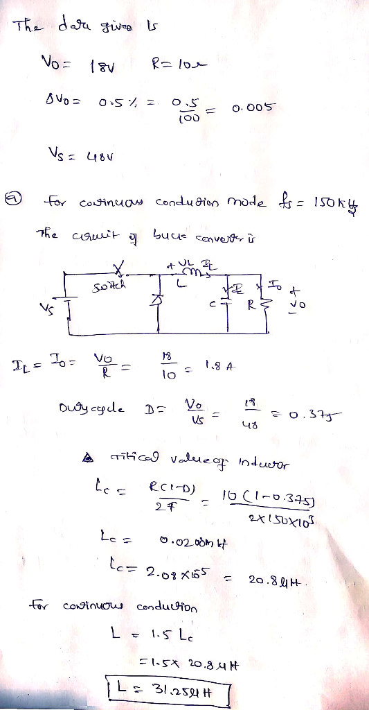
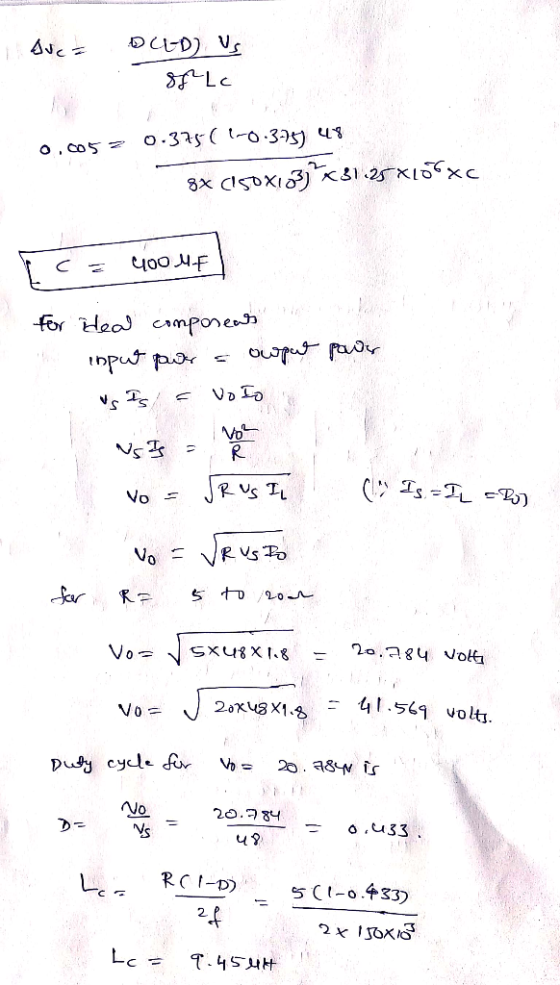
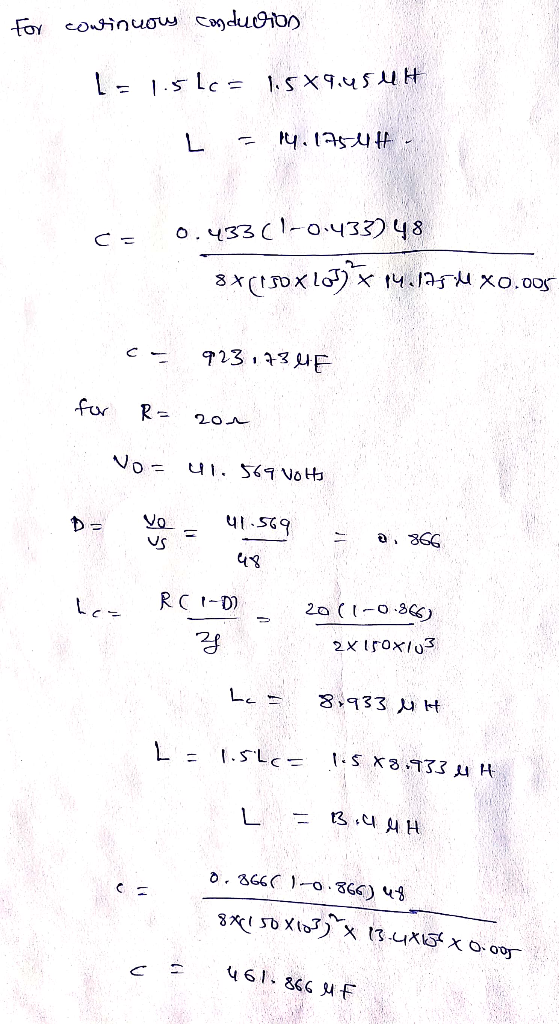
Buck Converter Design Design a buck converter to produce an output voltage of 18 V across a 10-Ω load resistor. The output voltage ripple must not exceed 0.5 percent. The de supply is 48 V. Design for continuous inductor current. a. What is the limitation on the load resistance for continuous-current operation? b. What would be the range of output voltage for a load resistance range of 5 to 20 ohm? c. Redesign the converter so inductor current remains continuous for a load resistance...
design buck convertor
Design a buck converter to produce an output voltage of 24 V across a 10 ohm load resistor. The output voltage ripple must not exceed 0.4 percent. The dc supply is 50 V. Design for continuous inductor current. Specify the duty ratio. Find the values of the inductor and capacitor, the peak voltage rating of each device, and the rms current in the inductor and capacitor. Assume ideal components.
Design a buck converter with the following specifications: Input voltage = 311 V Output voltage =...
Design a buck converter with the following specifications: Input voltage = 311 V Output voltage = 48 V Output voltage ripple = +/- 0.1% Maximum output current = 10 A Inductor current ripple = 5% Switching frequency = 100 kHz a) Select the inductor and the output capacitor and show a capture of the behaviour b) Calculate power losses assuming a rising time of 100 ns, a falling time of 100 ns, and Rdson = 10 mΩ. c) Calculate output...
18 marks load with a power of 25.6 W.The cy f is 40kHz. sign a buck-boost converter to produce an output voltage of 16V a put voltage ripple must not exceed 1%. The dc input voltage is 24V. Th e swit...
 18 marks load with a power of 25.6 W.The cy f is 40kHz. sign a buck-boost converter to produce an output voltage of 16V a put voltage ripple must not exceed 1%. The dc input voltage is 24V. Th e switching frequen 121 a) the duty ratio b) Find the size of the inductor so that the maximum inductor current c) the size of the capacitor d) Assume L=1 00μH and the switching frequency fis variable. 141 121 Lma 10A...
1) (6 points) It is desired to design a 50 W buck-boost converter to regulate its...
 1) (6 points) It is desired to design a 50 W buck-boost converter to regulate its output voltage at 26V from a solar panel whose output voltage varies between 20 and 40 V. The desired switching frequency is 20 kHz. The ripple current in the inductor should remain within +/-0.1 A, and the output voltage ripple should not exceed +/- 2%. a. Determine the duty cycle range for operating this converter. b. Design this buck-boost converter by finding lower limits...
Buck Converter Question Q3. A Buck converter is used to produce a regulated 10V, 5A DC...
 Buck Converter Question
Q3. A Buck converter is used to produce a regulated 10V, 5A DC power supply from a variable DC source with an nominal input voltage of Vin = 20V±5V. The Buck converter switches at 250kHz, and operates entirely in the continuous conduction mode. The output filter capacitance is C1.0uF 3.a. Draw the circuit topology for the Buck converter. Ensure that your circuit includes the input DC source, the output load resistance, the switching devices (i.e. MOSFET and...
Buck Converter Question
Q3. A Buck converter is used to produce a regulated 10V, 5A DC power supply from a variable DC source with an nominal input voltage of Vin = 20V±5V. The Buck converter switches at 250kHz, and operates entirely in the continuous conduction mode. The output filter capacitance is C1.0uF 3.a. Draw the circuit topology for the Buck converter. Ensure that your circuit includes the input DC source, the output load resistance, the switching devices (i.e. MOSFET and...
A buck converter is used to have low output voltage from the high input source to...
 A buck converter is used to have low output voltage from the high input source to low output voltage. The estimated power output is at 25 kW with the switching frequency of 25 kHz. Design the buck converter as by finding and following specifications consider the ripple of the output is set at 1% (i) Calculate the duty ratio of the buck converter (1 mark) (ii) Determine the minimum requirement for the inductor and the capacitor (5 marks) (iii) Determine...
2. Renewable energy system requires a boost converter with input voltage variation of 18 V to 42 ...
 2. Renewable energy system requires a boost converter with input voltage variation of 18 V to 42 V (de) and gives output of 120 V at 0.6 kW. For the converter the switching frequency is set at 50 kHz. a) Find the operating duty cycle range for each switch of the converter0 marks b) 196 What is the inductor value which should keep inductor current variation below under all input voltages [30 marks] c) Find the capacitor value which should...
Afs 4. Design a Buck-Boost Converter to convert 10 vdc to -20 vdc, using the switching...
 Afs 4. Design a Buck-Boost Converter to convert 10 vdc to -20 vdc, using the switching frequency of 50 kHz for a load resistance of 50 22. (a) What is the duty ratio, D? (b) What is the minimum value for the inductor to be utilized? (C) Assuming to utilize an inductor with double the minimum value, determine the maximum inductor current. (d) For an output voltage ripple of 3%, determine the value of the output capacitor, non
Design a DC-DC boost converter, shown below, that converts an unregulated supply of 12.0 Vak into a load voltage of...
 Design a DC-DC boost converter, shown below, that converts an unregulated supply of 12.0 Vak into a load voltage of 30.0 Ve and load current of 0.25 A. The switching frequency of the transistor is 100 kHz. The transistor has an on-resistance of 0.15 Ω and the diode drops 0.7 V when it is conducting. The voltage ripple (Av) is taken as 20 mVpp The circuit has 80% conversion efficiency. Find the DC input-current (Iden), duty-cycle (D), inductance (L), power-dissipation...
 18 marks load with a power of 25.6 W.The cy f is 40kHz. sign a buck-boost converter to produce an output voltage of 16V a put voltage ripple must not exceed 1%. The dc input voltage is 24V. Th e switching frequen 121 a) the duty ratio b) Find the size of the inductor so that the maximum inductor current c) the size of the capacitor d) Assume L=1 00μH and the switching frequency fis variable. 141 121 Lma 10A...
 1) (6 points) It is desired to design a 50 W buck-boost converter to regulate its output voltage at 26V from a solar panel whose output voltage varies between 20 and 40 V. The desired switching frequency is 20 kHz. The ripple current in the inductor should remain within +/-0.1 A, and the output voltage ripple should not exceed +/- 2%. a. Determine the duty cycle range for operating this converter. b. Design this buck-boost converter by finding lower limits...
 Buck Converter Question
Q3. A Buck converter is used to produce a regulated 10V, 5A DC power supply from a variable DC source with an nominal input voltage of Vin = 20V±5V. The Buck converter switches at 250kHz, and operates entirely in the continuous conduction mode. The output filter capacitance is C1.0uF 3.a. Draw the circuit topology for the Buck converter. Ensure that your circuit includes the input DC source, the output load resistance, the switching devices (i.e. MOSFET and...
Buck Converter Question
Q3. A Buck converter is used to produce a regulated 10V, 5A DC power supply from a variable DC source with an nominal input voltage of Vin = 20V±5V. The Buck converter switches at 250kHz, and operates entirely in the continuous conduction mode. The output filter capacitance is C1.0uF 3.a. Draw the circuit topology for the Buck converter. Ensure that your circuit includes the input DC source, the output load resistance, the switching devices (i.e. MOSFET and...
 A buck converter is used to have low output voltage from the high input source to low output voltage. The estimated power output is at 25 kW with the switching frequency of 25 kHz. Design the buck converter as by finding and following specifications consider the ripple of the output is set at 1% (i) Calculate the duty ratio of the buck converter (1 mark) (ii) Determine the minimum requirement for the inductor and the capacitor (5 marks) (iii) Determine...
 2. Renewable energy system requires a boost converter with input voltage variation of 18 V to 42 V (de) and gives output of 120 V at 0.6 kW. For the converter the switching frequency is set at 50 kHz. a) Find the operating duty cycle range for each switch of the converter0 marks b) 196 What is the inductor value which should keep inductor current variation below under all input voltages [30 marks] c) Find the capacitor value which should...
 Afs 4. Design a Buck-Boost Converter to convert 10 vdc to -20 vdc, using the switching frequency of 50 kHz for a load resistance of 50 22. (a) What is the duty ratio, D? (b) What is the minimum value for the inductor to be utilized? (C) Assuming to utilize an inductor with double the minimum value, determine the maximum inductor current. (d) For an output voltage ripple of 3%, determine the value of the output capacitor, non
 Design a DC-DC boost converter, shown below, that converts an unregulated supply of 12.0 Vak into a load voltage of 30.0 Ve and load current of 0.25 A. The switching frequency of the transistor is 100 kHz. The transistor has an on-resistance of 0.15 Ω and the diode drops 0.7 V when it is conducting. The voltage ripple (Av) is taken as 20 mVpp The circuit has 80% conversion efficiency. Find the DC input-current (Iden), duty-cycle (D), inductance (L), power-dissipation...
Most questions answered within 3 hours.
-
Tennis champion Maria Sharapova is capable of serving a tennis
ball at 126 mph.
b) What...
asked 1 minute ago -
The electric potential V in the space between the plates of a
given vacuum tube is...
asked 10 minutes ago -
The Hydroboration-Oxidation of an Alkene to Yield 1-Octanol.
1-octene to 1-octanol using BH3-THF
What might be...
asked 15 minutes ago -
You draw and keep a single bill from a hat that contains a
$11, $55, $20...
asked 32 minutes ago -
Write a Java program that has the following methods:
findSum - a method that takes in...
asked 33 minutes ago -
A coffee cup calorimeter initially contains 135g of water at
22.0oC. Calcium chloride (21.0g) at the...
asked 36 minutes ago -
A patient is having a magnetic resonance imaging scan (an MRI)
and has neglected to remove...
asked 38 minutes ago -
A student takes a multiple-choice test that has 10 questions.
Each question has two choices. The...
asked 1 hour ago -
Willie Keeler has a lifetime batting average of 0.341. Assume
that Willie Keeler came to bat...
asked 1 hour ago -
Which of the following has the highest boiling point?
A) 0.5m NaCl
B) 0.5m C6H12O6
C)...
asked 1 hour ago -
12. A firm is producing at an output level where
AR = MC > AC >...
asked 1 hour ago -
Radovilsky Manufacturing Company, in Hayward, California,
makes flashing lights for toys. The company operates its production...
asked 1 hour ago