
Homework Answers


Add Answer to:
2. In the following circuit, v, 20 Vrms (rms value). a) Determine the value of capacitor needed to provide filtering so that the voltage does not drop below 26 V. The load resistance Rioad may var...
2. In the following circuit, v,-20 Vrms (rms value). a) Determine the value of capacitor needed to provide filtering so that the voltage does not drop below 26 V. The load resistance Rioad may va...
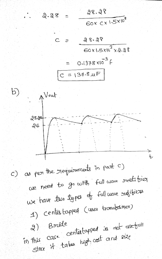
 2. In the following circuit, v,-20 Vrms (rms value). a) Determine the value of capacitor needed to provide filtering so that the voltage does not drop below 26 V. The load resistance Rioad may vary from 1.5 k2 to 2.5 k2. Assume the diode is ideal (Vox -0 V). b) Sketch v, and the output Vour waveforms. c) The filter capacitor often represents a significant economic factor in terms of cost, size, and weight in the design of rectifier circuit....
Be detailed in solving the question please 6. Rectifier] Given the rectifier circuit with filter capacitor...
 Be detailed in solving the question please
6. Rectifier] Given the rectifier circuit with filter capacitor where Vs = 15 cos(2760) V, the load is represented by R = 25 k92. Assume ideal diode operation, and answer the following questions: a What is the name of this type of rectifier circuit? b) If we want the reduction in voltage between the rectified Vout peaks (ripple) to be only 0.1 V, what value for C should we use? c) On the...
Be detailed in solving the question please
6. Rectifier] Given the rectifier circuit with filter capacitor where Vs = 15 cos(2760) V, the load is represented by R = 25 k92. Assume ideal diode operation, and answer the following questions: a What is the name of this type of rectifier circuit? b) If we want the reduction in voltage between the rectified Vout peaks (ripple) to be only 0.1 V, what value for C should we use? c) On the...
2. Consider the full-wave rectifier circuit in below. The output resistance is R - 125 12,...
 2. Consider the full-wave rectifier circuit in below. The output resistance is R - 125 12, each diode cut-in voltage is V, -0.7 V, and the frequency of the input signal is 60 Hz. If a filter capacitor will be connected in parallel with R. The magnitude of the peak output voltage is to be 15 V and the ripple voltage is to be no more than 0.35 V. (a) Determine the rms value of vs and (b) the required...
Consider the single-phase full-wave rectifier circuit shown below with a sinusoidal input vs 120 Vrms at...
 Consider the single-phase full-wave rectifier circuit shown below with a sinusoidal input vs 120 Vrms at 60 Hz and a load R= 250 TiD DAZ 40 AD AD ww D (a) (b) Consider adding a filter capacitor to the full-wave rectifier in Problem 3 to reduce the output ripple (a) Calculate the minimum value of capacitance required to reduce the output voltage ripple to 1 % of the average value (b) Calculate the average output current (c) Calculate the average...
4.70 A full-wave bridge-rectifier circuit with a 500-22 load operates from a 120-V (rms) 60-Hz household...
 4.70 A full-wave bridge-rectifier circuit with a 500-22 load operates from a 120-V (rms) 60-Hz household supply through a 6-to-1 step-down transformer having a single Secondary winding. It uses four diodes, each of which can be modeled to have a 0.7-V drop for any current. What is the peak value of the rectified voltage across the load? For what fraction of a cycle does each diode conduct? What is the average voltage across the load? What is the average current...
Design a FULL WAVE BRIDGE RECTIFIER circuit that will: Take 120volts ac, 60 hz, sinusoidal waveform...
 Design a FULL WAVE BRIDGE RECTIFIER circuit that will:
Take 120volts ac, 60 hz, sinusoidal waveform and convert
it to a “regulated “dc value
giving 12 volts +, - 1 volt across a 2000-ohm output
load resistor with no more than 2%
ripple voltage.
You may assume:
a. An ideal power transformer as discussed in class.
b. For hand computations, you must assume a diode given by
Figure 4.8 page 185.
c. A filter capacitor sized per the textbook equation...
Design a FULL WAVE BRIDGE RECTIFIER circuit that will:
Take 120volts ac, 60 hz, sinusoidal waveform and convert
it to a “regulated “dc value
giving 12 volts +, - 1 volt across a 2000-ohm output
load resistor with no more than 2%
ripple voltage.
You may assume:
a. An ideal power transformer as discussed in class.
b. For hand computations, you must assume a diode given by
Figure 4.8 page 185.
c. A filter capacitor sized per the textbook equation...
 2. In the following circuit, v,-20 Vrms (rms value). a) Determine the value of capacitor needed to provide filtering so that the voltage does not drop below 26 V. The load resistance Rioad may vary from 1.5 k2 to 2.5 k2. Assume the diode is ideal (Vox -0 V). b) Sketch v, and the output Vour waveforms. c) The filter capacitor often represents a significant economic factor in terms of cost, size, and weight in the design of rectifier circuit....
 Be detailed in solving the question please
6. Rectifier] Given the rectifier circuit with filter capacitor where Vs = 15 cos(2760) V, the load is represented by R = 25 k92. Assume ideal diode operation, and answer the following questions: a What is the name of this type of rectifier circuit? b) If we want the reduction in voltage between the rectified Vout peaks (ripple) to be only 0.1 V, what value for C should we use? c) On the...
Be detailed in solving the question please
6. Rectifier] Given the rectifier circuit with filter capacitor where Vs = 15 cos(2760) V, the load is represented by R = 25 k92. Assume ideal diode operation, and answer the following questions: a What is the name of this type of rectifier circuit? b) If we want the reduction in voltage between the rectified Vout peaks (ripple) to be only 0.1 V, what value for C should we use? c) On the...
 2. Consider the full-wave rectifier circuit in below. The output resistance is R - 125 12, each diode cut-in voltage is V, -0.7 V, and the frequency of the input signal is 60 Hz. If a filter capacitor will be connected in parallel with R. The magnitude of the peak output voltage is to be 15 V and the ripple voltage is to be no more than 0.35 V. (a) Determine the rms value of vs and (b) the required...
 Consider the single-phase full-wave rectifier circuit shown below with a sinusoidal input vs 120 Vrms at 60 Hz and a load R= 250 TiD DAZ 40 AD AD ww D (a) (b) Consider adding a filter capacitor to the full-wave rectifier in Problem 3 to reduce the output ripple (a) Calculate the minimum value of capacitance required to reduce the output voltage ripple to 1 % of the average value (b) Calculate the average output current (c) Calculate the average...
 4.70 A full-wave bridge-rectifier circuit with a 500-22 load operates from a 120-V (rms) 60-Hz household supply through a 6-to-1 step-down transformer having a single Secondary winding. It uses four diodes, each of which can be modeled to have a 0.7-V drop for any current. What is the peak value of the rectified voltage across the load? For what fraction of a cycle does each diode conduct? What is the average voltage across the load? What is the average current...
 Design a FULL WAVE BRIDGE RECTIFIER circuit that will:
Take 120volts ac, 60 hz, sinusoidal waveform and convert
it to a “regulated “dc value
giving 12 volts +, - 1 volt across a 2000-ohm output
load resistor with no more than 2%
ripple voltage.
You may assume:
a. An ideal power transformer as discussed in class.
b. For hand computations, you must assume a diode given by
Figure 4.8 page 185.
c. A filter capacitor sized per the textbook equation...
Design a FULL WAVE BRIDGE RECTIFIER circuit that will:
Take 120volts ac, 60 hz, sinusoidal waveform and convert
it to a “regulated “dc value
giving 12 volts +, - 1 volt across a 2000-ohm output
load resistor with no more than 2%
ripple voltage.
You may assume:
a. An ideal power transformer as discussed in class.
b. For hand computations, you must assume a diode given by
Figure 4.8 page 185.
c. A filter capacitor sized per the textbook equation...
Most questions answered within 3 hours.
-
1. Which region has taken the lead in the world of
e-waste handling?
a) European Union...
asked 1 minute ago -
If you’re standing at the bottom of a hill and asked to evaluate
it while being...
asked 8 minutes ago -
A 8.15- g bullet from a 9-mm pistol has a velocity of 366.0 m/s.
It strikes...
asked 1 hour ago -
The outstanding bonds of Alpha Extracts have a yield to maturity
of 7.4 percent and a...
asked 1 hour ago -
The Problem: The Case of the Harmonizing Vacations
Your CEO is exploring partnering with a European...
asked 2 hours ago -
A chemical equation is balanced by adding coefficients in front
of some formulas so that the...
asked 2 hours ago -
From the literature (reference your sources): What are the
lattice parameters of calcite and aragonite? Why...
asked 3 hours ago -
Your system is rejecting the question am asking which is
preceded by a case study. It...
asked 3 hours ago -
3. On January 2, 2000, Larry creates a trust with himself as
trustee. Larry as trustee...
asked 3 hours ago -
A member of the volleyball team spikes the ball. During this
process, she changes the velocity...
asked 3 hours ago -
Are adult gamers less likely to use a gaming console (Xbox,
PlayStation, Wii, etc...) than teen...
asked 4 hours ago -
The University of
Texas recently reported that 43% of college students aged 18-24
would spend their...
asked 4 hours ago