

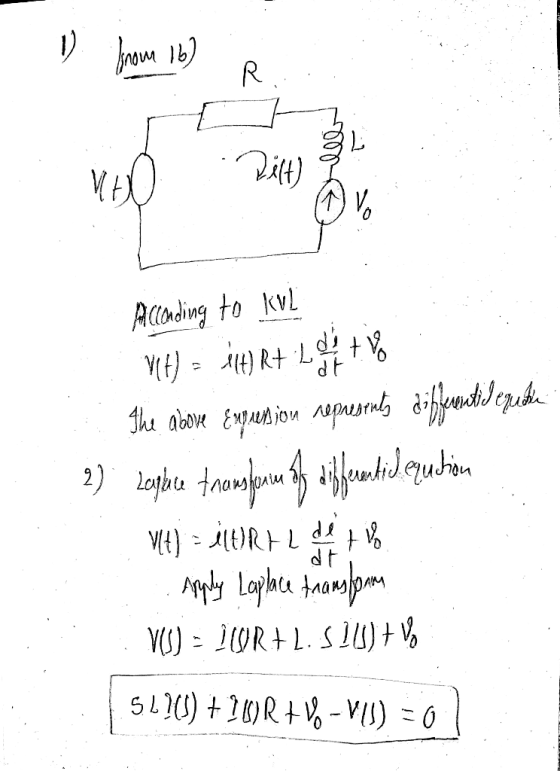
electromagnetic coupling constant, as shown below In addition, an ideal spring with Hooke law constant of K is attached to mass, which opposes the motion of the mass and returns the mass to its initial position when the current no longer flows in the winding Therefore we can represent the electrical elements of the system as shown in figure 1(b) and the mechanical elements as shown in figure 1(c). The electrical and mechanical element are linked (glued together) by the two equations above The Problem The objective of this assignment is to determine y(t) when r(t) plunger when the input voltage is the unit step). U(t) (ie the movement of the The Method To do this you will separately determine, e the Laplace transform for the current I(s), and the Laplace transform for the movement of the mass for a given force Fs). Then you will "glue these two expressions together using equation 1 Once that is completed, the expression then must be rearranged so we have an expression describing Y(s). Finally we take the inverse Laplace transform to give yt), and which you will plot using Sailab 1. Determine the differential equation which describes the electrical lumped circuit model in figure 1(b) 2. Take the Laplace transform of your differential equation and rearrange it to produce an expression for I(s) 3. Determine the differential equation which relates fit) and yt) in figure 1(c) 4 Take the Laplace transform of your previous differential equation 5. Substitute your expression an expression for y(s) for I() in to the previous expression. and then it rearrange to determine 6. For this solenoid RL and therefore the electrical time constant is negligible (in a similar fashion to the simplification made in the motes for the derivation of the transfer function for small DC motors). Thus you can simplity your transfer function by top and bottom of your expression by R and then removing any product terms which include 7. Assuming M-0.kg, R- 52. K- 0.1 and.N Ivolt-sec/coulomb, substitute in the values for the parameters and take the inverse Laplace transform to determine yr 8. Plot the time response y(t) using Scilab. Include your Scilab Code in your answer Each step above, should be labelled in your report
Homework Answers


Add Answer to:
winkngs spring i(t) v(t) st VEE Figure 1: (a)Solenoid with retu spring. (b) Equivalent lumped electrical cireuit (...
Consider the electromechanical dynamic system shown in Figure 1(a). It consists of a cart of mass...
 This assignment is for my Engr dynamics systems class.
Consider the electromechanical dynamic system shown in Figure 1(a). It consists of a cart of mass m moving without slipping on a linear ground track. The cart is equipped with an armature-controlled DC motor, which is coupled to a rack and pinion mechanism to convert the rotational motion to translation and to create the driving force for the system. Figure 1(b) shows the simplified equivalent electric circuit and the mechanical model...
This assignment is for my Engr dynamics systems class.
Consider the electromechanical dynamic system shown in Figure 1(a). It consists of a cart of mass m moving without slipping on a linear ground track. The cart is equipped with an armature-controlled DC motor, which is coupled to a rack and pinion mechanism to convert the rotational motion to translation and to create the driving force for the system. Figure 1(b) shows the simplified equivalent electric circuit and the mechanical model...
The mechanical system shown in the figure below is excited by a sinusoidal force f(t)-Fi cos(ut...
 The mechanical system shown in the figure below is excited by a sinusoidal force f(t)-Fi cos(ut + ?) N. The differential equation of the displacement x(t) is Use phasor techniques to solve for the displacement phasor Xin terms of the excitation frequency ? , and the mechanical elements M = 0.1 kg, D = 8 N-s/m , and K = 2,000 N/m . If Fi-10 N and ?? = 30°, determine the excitation frequency w (in rad/s) at which the...
43 Questions 1. Using Figure 4-2, determine the electrical relationship characterizing a standard DC motor. Express...
 43 Questions 1. Using Figure 4-2, determine the electrical relationship characterizing a standard DC motor. Express the relationship in the Laplace domain. L. i,o, M ry Figure 4-2 DC Motor Electric Circuit 2. Determine and evaluate the motor electrical time constant, τ.. This is done by assuming that the shaft is stationary. You can find the parameters of the motor in Table B-1. 3. Assume τ. is negligible and simplify the motor electrical relationship determined in question 1. What is...
. Question 1 (40 marks) This question asks you to demonstrate your understanding of the following...
 . Question 1 (40 marks) This question asks you to demonstrate your understanding of the following learning objectives LO 1.6 Express the Laplace Transform of common mathematical functions and linear ordinary differential equations using both first principles and mathematical tables. LO 1.7 Construct transfer functions for linear dynamic systems from (i) differential equations and (ii) reduction of block diagrams. LO1.8 Determine the time response of a Linear SISO system to an arbitrary input and having arbitrary initial conditions. LO 1.9...
Engineering circuit analysis by Hayt 8th edition question 27 and figure 9.43 I think 10u(1-t) means 10 (for t<1)...
 Engineering circuit analysis by Hayt
8th edition
question 27 and figure 9.43
I think 10u(1-t) means 10 (for t<1) and 0
(for t>1)
then, I can't remove this current source because it
continuously make 10micro A
(at t=500ms, t=1.002ms)
I don't know what's wrong now..
366 26. For the circuit of Fig. 9,43, 1 30-) mA. (a) Select R, so th O)6 V (b) Compute e2 ms). (c) Determine the settling, time of t capacitor voltage. (d) Is the inductor...
Engineering circuit analysis by Hayt
8th edition
question 27 and figure 9.43
I think 10u(1-t) means 10 (for t<1) and 0
(for t>1)
then, I can't remove this current source because it
continuously make 10micro A
(at t=500ms, t=1.002ms)
I don't know what's wrong now..
366 26. For the circuit of Fig. 9,43, 1 30-) mA. (a) Select R, so th O)6 V (b) Compute e2 ms). (c) Determine the settling, time of t capacitor voltage. (d) Is the inductor...
 This assignment is for my Engr dynamics systems class.
Consider the electromechanical dynamic system shown in Figure 1(a). It consists of a cart of mass m moving without slipping on a linear ground track. The cart is equipped with an armature-controlled DC motor, which is coupled to a rack and pinion mechanism to convert the rotational motion to translation and to create the driving force for the system. Figure 1(b) shows the simplified equivalent electric circuit and the mechanical model...
This assignment is for my Engr dynamics systems class.
Consider the electromechanical dynamic system shown in Figure 1(a). It consists of a cart of mass m moving without slipping on a linear ground track. The cart is equipped with an armature-controlled DC motor, which is coupled to a rack and pinion mechanism to convert the rotational motion to translation and to create the driving force for the system. Figure 1(b) shows the simplified equivalent electric circuit and the mechanical model...
 The mechanical system shown in the figure below is excited by a sinusoidal force f(t)-Fi cos(ut + ?) N. The differential equation of the displacement x(t) is Use phasor techniques to solve for the displacement phasor Xin terms of the excitation frequency ? , and the mechanical elements M = 0.1 kg, D = 8 N-s/m , and K = 2,000 N/m . If Fi-10 N and ?? = 30°, determine the excitation frequency w (in rad/s) at which the...
 43 Questions 1. Using Figure 4-2, determine the electrical relationship characterizing a standard DC motor. Express the relationship in the Laplace domain. L. i,o, M ry Figure 4-2 DC Motor Electric Circuit 2. Determine and evaluate the motor electrical time constant, τ.. This is done by assuming that the shaft is stationary. You can find the parameters of the motor in Table B-1. 3. Assume τ. is negligible and simplify the motor electrical relationship determined in question 1. What is...
 . Question 1 (40 marks) This question asks you to demonstrate your understanding of the following learning objectives LO 1.6 Express the Laplace Transform of common mathematical functions and linear ordinary differential equations using both first principles and mathematical tables. LO 1.7 Construct transfer functions for linear dynamic systems from (i) differential equations and (ii) reduction of block diagrams. LO1.8 Determine the time response of a Linear SISO system to an arbitrary input and having arbitrary initial conditions. LO 1.9...
 Engineering circuit analysis by Hayt
8th edition
question 27 and figure 9.43
I think 10u(1-t) means 10 (for t<1) and 0
(for t>1)
then, I can't remove this current source because it
continuously make 10micro A
(at t=500ms, t=1.002ms)
I don't know what's wrong now..
366 26. For the circuit of Fig. 9,43, 1 30-) mA. (a) Select R, so th O)6 V (b) Compute e2 ms). (c) Determine the settling, time of t capacitor voltage. (d) Is the inductor...
Engineering circuit analysis by Hayt
8th edition
question 27 and figure 9.43
I think 10u(1-t) means 10 (for t<1) and 0
(for t>1)
then, I can't remove this current source because it
continuously make 10micro A
(at t=500ms, t=1.002ms)
I don't know what's wrong now..
366 26. For the circuit of Fig. 9,43, 1 30-) mA. (a) Select R, so th O)6 V (b) Compute e2 ms). (c) Determine the settling, time of t capacitor voltage. (d) Is the inductor...
Most questions answered within 3 hours.
-
10. Complete the table below
only using hexadecimal numbers:
AL CODE
EBX
EAX
[EAX]
mov eax,...
asked 44 seconds from now -
trust is best established through the combination of ------and
------- .
1. magnanimity and justice
2....
asked 13 minutes ago -
Blood pressure is normally taken on the upper arm at the level
of the heart. Suppose,...
asked 12 minutes ago -
Suppose that the satellite around the earth has an orbit that is
24 KM larger in...
asked 16 minutes ago -
Calculate the [OH (aq)] in limes which have a [H3O*(aq)] of 1.3 x
10 mol/L
asked 14 minutes ago -
A nozzle with a radius of 0.250 cm is attached to a garden hose
with a...
asked 25 minutes ago -
PLEASE do not use any loops for the program; only recursion is
allowed
4. Write a...
asked 34 minutes ago -
Please help me with me. I did the first part to write the operations but in...
asked 31 minutes ago -
Use Cryptool to find the Cryptographic SHA-1 hash value of the
string "abc". The calculator is...
asked 35 minutes ago -
You are attempting to calculate a firm’s free cash flow to
equity. You know the following...
asked 1 hour ago -
the following reaction occurs in a balloon containing
N2O2 gas
N2O4(g)=2NO2(g)
will the volume of the...
asked 2 hours ago -
answer the questions throughout this program
public class Day implements Comparable {
Private Boolean atWork;...
asked 2 hours ago