
Homework Answers


Add Answer to:
SAN4701 OCT/NOV 2016 QUESTION 3 The frame shown in the Figure 3 is having a fixed support at A and a hinged at support...
SAN4701 OCT/NOV 2017 QUESTION 1 The beam shown in Figure 1 is fixed at support A and support C, support B is a roller s...
 SAN4701 OCT/NOV 2017 QUESTION 1 The beam shown in Figure 1 is fixed at support A and support C, support B is a roller support. Use the stiffness matrix method to determine the. Member stiffness matrix 11 1.2 Structure and load matrix (10) 13 Displacement matrix Reactions at the support 14 15. Moments at the fixed supports El is constant along the length of the beam 18 kN 10 kN 20 m 10 m 1 15 m15 m Figure 1...
SAN4701 OCT/NOV 2014 QUESTION 1 Determine the member forces in the symmetrical truss shown in Figure 1 The panels are a...
 SAN4701 OCT/NOV 2014 QUESTION 1 Determine the member forces in the symmetrical truss shown in Figure 1 The panels are assumed to be square with all the members having a constant EA of 35 x 103 kN [30 MARKS] 4M 10 KN
SAN4701 OCT/NOV 2014 QUESTION 1 Determine the member forces in the symmetrical truss shown in Figure 1 The panels are assumed to be square with all the members having a constant EA of 35 x 103 kN [30...
SAN4701 OCT/NOV 2014 QUESTION 1 Determine the member forces in the symmetrical truss shown in Figure 1 The panels are assumed to be square with all the members having a constant EA of 35 x 103 kN [30 MARKS] 4M 10 KN
SAN4701 OCT/NOV 2014 QUESTION 1 Determine the member forces in the symmetrical truss shown in Figure 1 The panels are assumed to be square with all the members having a constant EA of 35 x 103 kN [30...
QUESTION 3 The truss shown in the Figure 3 is having hinged supports at A and B, assuming that the EA is constant for a...
 QUESTION 3 The truss shown in the Figure 3 is having hinged supports at A and B, assuming that the EA is constant for all the members. Use a flexibility method to determine the forces in each member and reactions at the supports. 80 kN 5 m 5 m 5 m 5 m Figure 3 130 marks) Total Marks [100
QUESTION 3 The truss shown in the Figure 3 is having hinged supports at A and B, assuming that the...
QUESTION 3 The truss shown in the Figure 3 is having hinged supports at A and B, assuming that the EA is constant for all the members. Use a flexibility method to determine the forces in each member and reactions at the supports. 80 kN 5 m 5 m 5 m 5 m Figure 3 130 marks) Total Marks [100
QUESTION 3 The truss shown in the Figure 3 is having hinged supports at A and B, assuming that the...
SAN4701 OCT/NOV 2013 QUESTION 3 (30 marks) Determine the member forces and vertical deflection at node C in the truss s...
 SAN4701 OCT/NOV 2013 QUESTION 3 (30 marks) Determine the member forces and vertical deflection at node C in the truss shown in Figure 3. Material property is constant throughout the members i.e EA -50 x 10° KN. 2 8 kN 3 m 4 4 m
SAN4701 OCT/NOV 2013 QUESTION 3 (30 marks) Determine the member forces and vertical deflection at node C in the truss shown in Figure 3. Material property is constant throughout the members i.e EA -50 x...
SAN4701 OCT/NOV 2013 QUESTION 3 (30 marks) Determine the member forces and vertical deflection at node C in the truss shown in Figure 3. Material property is constant throughout the members i.e EA -50 x 10° KN. 2 8 kN 3 m 4 4 m
SAN4701 OCT/NOV 2013 QUESTION 3 (30 marks) Determine the member forces and vertical deflection at node C in the truss shown in Figure 3. Material property is constant throughout the members i.e EA -50 x...
SAN4701 JAN/FEB 2015 QUESTION 1 The truss shown in Figure 1 is hinged at C, B and D It is acted upon at node A by a ver...
 SAN4701 JAN/FEB 2015 QUESTION 1 The truss shown in Figure 1 is hinged at C, B and D It is acted upon at node A by a vertically downward force of 3 kN and a honzontal force of 5 kN as shown in Figure 1 Use the method of strffness matrix and analyse for the following (a) Displacement at node A (16) (b) Reaction at the supports (c) Member forces (15) EA 300 x 103 kN and is constant for...
QUESTION 1 [25 marks A frame loaded with a uniformly distributed load at Member AB and...
 QUESTION 1 [25 marks A frame loaded with a uniformly distributed load at Member AB and point load at Member BC and joint B. It has pinned supports A and C, while joint B is fixed connected, as can be seen in Figure 1. Take E-200 GPa. a) Using the slope-deflection method, calculate the moments and illustrate the bending moment diagram. [15 marks) b) Then calculate the shear forces and sketch the shear force diagram. [10 marks) 22 KN 10...
SAN4701 JAN/FE8 2017 QUESTION 1 1 is having a hinge support at 1 and a roller support at 2. (E - 200 GPa) for all the m...
 SAN4701 JAN/FE8 2017 QUESTION 1 1 is having a hinge support at 1 and a roller support at 2. (E - 200 GPa) for all the members and the members 1, d 3 have their cross sectional areas as 4000 mm2, 4000 mm2 and 6000 mm2 The truss shown in Figure Assuming that E is constant respectively, use the matrix stiffness method to determine the following Number of degrees of freedom. a. (15) b. Structure stiffness matrıx. (10) c Member...
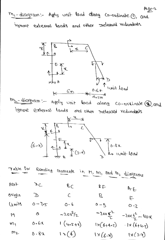
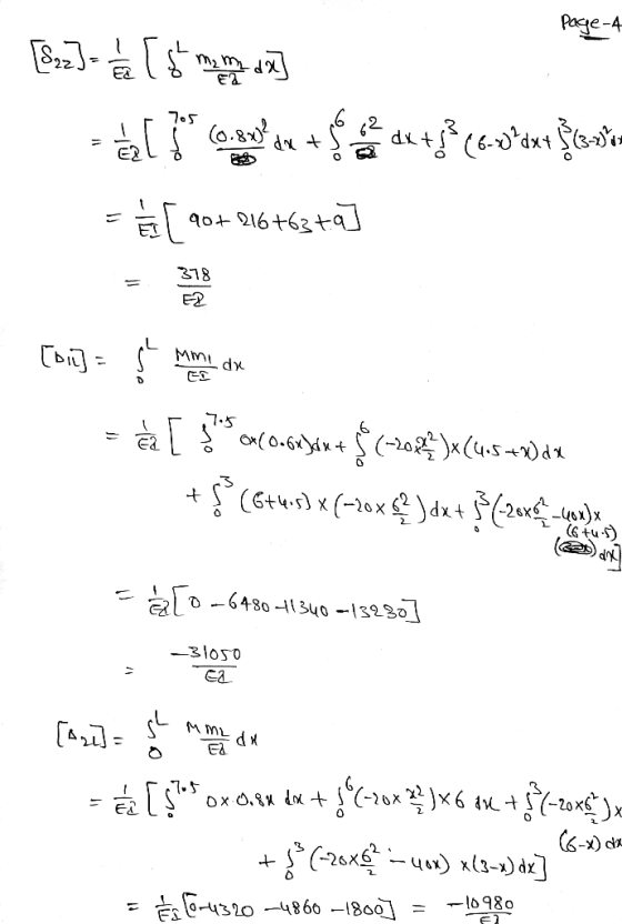
Q4 The steel frame is fixed at point D and supports a concentrated force of 64...
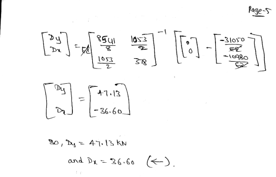
 Q4 The steel frame is fixed at point D and supports a concentrated force of 64 kN, as shown in Figure Q4a. Assume a fixed connection at C. Assume El is constant for all the members. a) Compute the vertical displacement at point A. [15pt] 64 kN A B 4 m 3 m 3 m D 7777 Figure Q4a b) A roller support is added to the frame at point A as shown in Figure Q4b. Determine the reactions at...
03: Given the statically indeterminate frame as shown in Fig. Q3 below, determine the member end...
 03: Given the statically indeterminate frame as shown in Fig. Q3 below, determine the member end moments and the support reactions of the frame using moment distribution method. Moment distribution to be done for 3 iterations of locking and unlocking cycle. A point load of 100KN is acting on span BC at 1/4 point of the span as shown. Support A and D are fixed supports. There is a roller support at joint C to prevent the frame from going...
The frame shown below is fixed at A and C, and is supported by a roller...
 The frame shown below is fixed at A and C, and is supported by a roller at B. Use the numbering shown for the members and joints and determine the support reactions at all supports of the frame using the Stiffness Method. The 10 kN force is applied at the middle of the beam, and the 12 kN/m load is uniformly distributed on the column Take E = 200 GPa, 1 = 300(109) mm+ and A = 10(10-) mm2 for...
 SAN4701 OCT/NOV 2017 QUESTION 1 The beam shown in Figure 1 is fixed at support A and support C, support B is a roller support. Use the stiffness matrix method to determine the. Member stiffness matrix 11 1.2 Structure and load matrix (10) 13 Displacement matrix Reactions at the support 14 15. Moments at the fixed supports El is constant along the length of the beam 18 kN 10 kN 20 m 10 m 1 15 m15 m Figure 1...
 SAN4701 OCT/NOV 2014 QUESTION 1 Determine the member forces in the symmetrical truss shown in Figure 1 The panels are assumed to be square with all the members having a constant EA of 35 x 103 kN [30 MARKS] 4M 10 KN
SAN4701 OCT/NOV 2014 QUESTION 1 Determine the member forces in the symmetrical truss shown in Figure 1 The panels are assumed to be square with all the members having a constant EA of 35 x 103 kN [30...
SAN4701 OCT/NOV 2014 QUESTION 1 Determine the member forces in the symmetrical truss shown in Figure 1 The panels are assumed to be square with all the members having a constant EA of 35 x 103 kN [30 MARKS] 4M 10 KN
SAN4701 OCT/NOV 2014 QUESTION 1 Determine the member forces in the symmetrical truss shown in Figure 1 The panels are assumed to be square with all the members having a constant EA of 35 x 103 kN [30...
 QUESTION 3 The truss shown in the Figure 3 is having hinged supports at A and B, assuming that the EA is constant for all the members. Use a flexibility method to determine the forces in each member and reactions at the supports. 80 kN 5 m 5 m 5 m 5 m Figure 3 130 marks) Total Marks [100
QUESTION 3 The truss shown in the Figure 3 is having hinged supports at A and B, assuming that the...
QUESTION 3 The truss shown in the Figure 3 is having hinged supports at A and B, assuming that the EA is constant for all the members. Use a flexibility method to determine the forces in each member and reactions at the supports. 80 kN 5 m 5 m 5 m 5 m Figure 3 130 marks) Total Marks [100
QUESTION 3 The truss shown in the Figure 3 is having hinged supports at A and B, assuming that the...
 SAN4701 OCT/NOV 2013 QUESTION 3 (30 marks) Determine the member forces and vertical deflection at node C in the truss shown in Figure 3. Material property is constant throughout the members i.e EA -50 x 10° KN. 2 8 kN 3 m 4 4 m
SAN4701 OCT/NOV 2013 QUESTION 3 (30 marks) Determine the member forces and vertical deflection at node C in the truss shown in Figure 3. Material property is constant throughout the members i.e EA -50 x...
SAN4701 OCT/NOV 2013 QUESTION 3 (30 marks) Determine the member forces and vertical deflection at node C in the truss shown in Figure 3. Material property is constant throughout the members i.e EA -50 x 10° KN. 2 8 kN 3 m 4 4 m
SAN4701 OCT/NOV 2013 QUESTION 3 (30 marks) Determine the member forces and vertical deflection at node C in the truss shown in Figure 3. Material property is constant throughout the members i.e EA -50 x...
 SAN4701 JAN/FEB 2015 QUESTION 1 The truss shown in Figure 1 is hinged at C, B and D It is acted upon at node A by a vertically downward force of 3 kN and a honzontal force of 5 kN as shown in Figure 1 Use the method of strffness matrix and analyse for the following (a) Displacement at node A (16) (b) Reaction at the supports (c) Member forces (15) EA 300 x 103 kN and is constant for...
 QUESTION 1 [25 marks A frame loaded with a uniformly distributed load at Member AB and point load at Member BC and joint B. It has pinned supports A and C, while joint B is fixed connected, as can be seen in Figure 1. Take E-200 GPa. a) Using the slope-deflection method, calculate the moments and illustrate the bending moment diagram. [15 marks) b) Then calculate the shear forces and sketch the shear force diagram. [10 marks) 22 KN 10...
 SAN4701 JAN/FE8 2017 QUESTION 1 1 is having a hinge support at 1 and a roller support at 2. (E - 200 GPa) for all the members and the members 1, d 3 have their cross sectional areas as 4000 mm2, 4000 mm2 and 6000 mm2 The truss shown in Figure Assuming that E is constant respectively, use the matrix stiffness method to determine the following Number of degrees of freedom. a. (15) b. Structure stiffness matrıx. (10) c Member...
 Q4 The steel frame is fixed at point D and supports a concentrated force of 64 kN, as shown in Figure Q4a. Assume a fixed connection at C. Assume El is constant for all the members. a) Compute the vertical displacement at point A. [15pt] 64 kN A B 4 m 3 m 3 m D 7777 Figure Q4a b) A roller support is added to the frame at point A as shown in Figure Q4b. Determine the reactions at...
 03: Given the statically indeterminate frame as shown in Fig. Q3 below, determine the member end moments and the support reactions of the frame using moment distribution method. Moment distribution to be done for 3 iterations of locking and unlocking cycle. A point load of 100KN is acting on span BC at 1/4 point of the span as shown. Support A and D are fixed supports. There is a roller support at joint C to prevent the frame from going...
 The frame shown below is fixed at A and C, and is supported by a roller at B. Use the numbering shown for the members and joints and determine the support reactions at all supports of the frame using the Stiffness Method. The 10 kN force is applied at the middle of the beam, and the 12 kN/m load is uniformly distributed on the column Take E = 200 GPa, 1 = 300(109) mm+ and A = 10(10-) mm2 for...
Most questions answered within 3 hours.
-
Calculate the number density of argon gas at a temperature of
24C and a pressure of...
asked 7 minutes ago -
Alternative
Classification
How to Estimate
Probabilities from Data? ( For continuous Attributes)
And How to generate...
asked 10 minutes ago -
An explosion breaks a 20.0-kg object into three parts. The
object is initially moving at a...
asked 1 hour ago -
Calculate the approximate number of residues of Rubisco, which
is involved in carbon fixation in plants,...
asked 2 hours ago -
Other decisions about scientific claims can have a much broader
impact.ENERGYarrow-10x10.png, environment, health, security - all...
asked 2 hours ago -
I need to write a research paper and work cited about this
topic: The United States...
asked 3 hours ago -
Hello! I was wondering if I could have some help?
If the vapor pressure of carvone...
asked 3 hours ago -
An economist wants to estimate the mean per capita income (in
thousands of dollars) for a...
asked 4 hours ago -
What would be the input/output characteristic of a circuit
obtained by putting two of your 2's-complementers...
asked 4 hours ago -
In Drosophila, the transition from the syncytial blastoderm
stage to the cellular blastoderm stage is a...
asked 4 hours ago -
Project management question:
Name 3 different types of resources (hint: humans are one
type)
asked 4 hours ago -
Consider the following reaction: C 2H 2( g) + 2H 2( g) C 2H 6(
g)...
asked 4 hours ago