

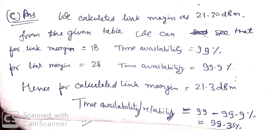
(b) For the information given below, calculate the link budget analysis for the wireless system, which will involve calculating the following: Received Power Link Margin Distance: 5 km 5.8GHz Fre Link : Point-to-Point, Line-of-Sight Tx power: +23dBm Antenna gain is 24dBi Assume negligible loss for cabling and connectors Receiver Sensitivity: 72dBm Assume that we are using the same antennas at the transmitter and the receiver side, the link budget calculations will be the same as the link budget in both directions is expected to be symmetrical. In cases where 2 types of antenna systems with different transmit power are used, we must perform two link budget analysis, one in each direction (c) For the calculated Link Margin at 5Km what can you say about the availability/reliability of the link based on the following Table which shows the relationship between the available link margin and link availability as a percentage of time Time Availability (Percentage) Link/Fade Margin 90 18 99.9 28 99.99 38 99.999 48
Homework Answers
b

c
Add Answer to:
Designing a High speed Wireless Data Link Line of Sight Link Budget Analysis Several major factors that can impact...
For the information given below, calculate the link budget analysis for the wireless system, which will involve calculat...
 For the information given below, calculate the link budget
analysis for the wireless system, which will involve calculating
the following:
• Received Power
• Link Margin
Assume that we are using the same antennas at the transmitter
and the receiver side, the link budget calculations will be the
same as the link budget in both directions is expected to be
symmetrical. In cases where 2 types of antenna systems with
different transmit power are used, we must perform two link...
For the information given below, calculate the link budget
analysis for the wireless system, which will involve calculating
the following:
• Received Power
• Link Margin
Assume that we are using the same antennas at the transmitter
and the receiver side, the link budget calculations will be the
same as the link budget in both directions is expected to be
symmetrical. In cases where 2 types of antenna systems with
different transmit power are used, we must perform two link...
For the information given below, calculate the link budget analysis for the wireless system, which will involve calculat...
For the information given below, calculate the link budget analysis for the wireless system, which will involve calculating the following: • Received Power • Link Margin Distance: 5 km Frequency: 5.8GHz Link Type: Point-to-Point, Line-of-Sight Tx power: +23dBm Antenna gain is 24dBi Assume negligible loss for cabling and connectors Receiver Sensitivity: -72dBm Assume that we are using the same antennas at the transmitter and the receiver side, the link budget calculations will be the same as the link budget in...
Complete the following table of link-budget analysis. The system bandwidth is 10 MHz. Show all required calculations. [Hint: Some of the values may not be required for calculating the final link margi...
 Complete the following table of link-budget analysis. The system
bandwidth is 10 MHz. Show all required calculations. [Hint: Some of
the values may not be required for calculating the final link
margin. But you are requested to calculate all unknown values on
the second column of the table.]
30 Transmit power (dBW) Transmit circuit losses (dB) Transmit antenna gain (dBi) EIRP (dBW) Path loss (dB) Received isotropic signal power (dBW) Received antenna gain (dBi) Received signal power P (dBW) System...
Complete the following table of link-budget analysis. The system
bandwidth is 10 MHz. Show all required calculations. [Hint: Some of
the values may not be required for calculating the final link
margin. But you are requested to calculate all unknown values on
the second column of the table.]
30 Transmit power (dBW) Transmit circuit losses (dB) Transmit antenna gain (dBi) EIRP (dBW) Path loss (dB) Received isotropic signal power (dBW) Received antenna gain (dBi) Received signal power P (dBW) System...
Consider the satellite relay link with the following parameters. Downlink EIRP of the satellite: 55 dBW...
 Consider the satellite relay link with the following parameters. Downlink EIRP of the satellite: 55 dBW Transmit frequency: Receiver noise temperature:700 K Receiver antenna gain Transmitter- receiver distance: 41,000 km System bandwidth: Total system losses (margin): 3 dB 2 GHz 0 dB 50 kHz (a) Find the received signal power in dBW (b) Find the receiver noise level in dBW (c) Calculate the signal-to-noise ratio at the receiver in dB
As a communications system engineer, you are asked to setup a communication system to serve a distance of 100m using an access point transmitting signals with power 20dBm at the frequency 2.4GHz. The...
 As a communications system engineer, you are asked to setup a communication system to serve a distance of 100m using an access point transmitting signals with power 20dBm at the frequency 2.4GHz. The antennas used at the transmitter and receiver side have the gains shown in the picture below. The coaxial cables used to interface the systems to the antennas have losses shown in the picture below What is the received signal power in dBm at the input of the...
Problem As a communications system engineer, you are asked to setup a communication system to serve...
 Problem As a communications system engineer, you are asked to setup a communication system to serve a distance of 100m using an access point transmitting signals with power 20dBm at the frequency 2.4GHz. The antennas used at the transmitter and receiver side have the gains shown in the picture below. The coaxial cables used to interface the systems to the antennas have losses shown in the picture below. What is the received signal power in dBm at the input of...
Problem #2: (40 points) Consider the following communication link. Both the transmitter and receivers are properly...
 Problem #2: (40 points) Consider the following communication link. Both the transmitter and receivers are properly matched to their respective antennas. Assume that the system nominal temperature is 290 K. A detailed block diagram of the receiver is shown in the figure Determine 1. The effective isotropic radiated power in dBm. 2. The space loss in dB 3. The communication link total losses in dB 4. What would be the received power at the receiver input in dBm? 5. What's...
Please answer the questions 1-4. Thank you. IV. Useful Equations G a2 4mR)2 Friis Transmission formula:...
 Please answer the questions
1-4. Thank you.
IV. Useful Equations G a2 4mR)2 Friis Transmission formula: = Gain of horn antenna: G0.7 3-dB beam width of a horn antenna: -k (rad) Far-field: R 2 (m where Ξ received power level (W) Pttransmitted power level (w) 4 Gt gain of transmit antenna Gr gain of receive antenna λ wavelength (m) R range (distance) between transmitter and receiver Ap = aperture of horn antenna (m2) beamwidth in x-z plane lxlength of antenna...
Please answer the questions
1-4. Thank you.
IV. Useful Equations G a2 4mR)2 Friis Transmission formula: = Gain of horn antenna: G0.7 3-dB beam width of a horn antenna: -k (rad) Far-field: R 2 (m where Ξ received power level (W) Pttransmitted power level (w) 4 Gt gain of transmit antenna Gr gain of receive antenna λ wavelength (m) R range (distance) between transmitter and receiver Ap = aperture of horn antenna (m2) beamwidth in x-z plane lxlength of antenna...
 For the information given below, calculate the link budget
analysis for the wireless system, which will involve calculating
the following:
• Received Power
• Link Margin
Assume that we are using the same antennas at the transmitter
and the receiver side, the link budget calculations will be the
same as the link budget in both directions is expected to be
symmetrical. In cases where 2 types of antenna systems with
different transmit power are used, we must perform two link...
For the information given below, calculate the link budget
analysis for the wireless system, which will involve calculating
the following:
• Received Power
• Link Margin
Assume that we are using the same antennas at the transmitter
and the receiver side, the link budget calculations will be the
same as the link budget in both directions is expected to be
symmetrical. In cases where 2 types of antenna systems with
different transmit power are used, we must perform two link...
 Complete the following table of link-budget analysis. The system
bandwidth is 10 MHz. Show all required calculations. [Hint: Some of
the values may not be required for calculating the final link
margin. But you are requested to calculate all unknown values on
the second column of the table.]
30 Transmit power (dBW) Transmit circuit losses (dB) Transmit antenna gain (dBi) EIRP (dBW) Path loss (dB) Received isotropic signal power (dBW) Received antenna gain (dBi) Received signal power P (dBW) System...
Complete the following table of link-budget analysis. The system
bandwidth is 10 MHz. Show all required calculations. [Hint: Some of
the values may not be required for calculating the final link
margin. But you are requested to calculate all unknown values on
the second column of the table.]
30 Transmit power (dBW) Transmit circuit losses (dB) Transmit antenna gain (dBi) EIRP (dBW) Path loss (dB) Received isotropic signal power (dBW) Received antenna gain (dBi) Received signal power P (dBW) System...
 Consider the satellite relay link with the following parameters. Downlink EIRP of the satellite: 55 dBW Transmit frequency: Receiver noise temperature:700 K Receiver antenna gain Transmitter- receiver distance: 41,000 km System bandwidth: Total system losses (margin): 3 dB 2 GHz 0 dB 50 kHz (a) Find the received signal power in dBW (b) Find the receiver noise level in dBW (c) Calculate the signal-to-noise ratio at the receiver in dB
 As a communications system engineer, you are asked to setup a communication system to serve a distance of 100m using an access point transmitting signals with power 20dBm at the frequency 2.4GHz. The antennas used at the transmitter and receiver side have the gains shown in the picture below. The coaxial cables used to interface the systems to the antennas have losses shown in the picture below What is the received signal power in dBm at the input of the...
 Problem As a communications system engineer, you are asked to setup a communication system to serve a distance of 100m using an access point transmitting signals with power 20dBm at the frequency 2.4GHz. The antennas used at the transmitter and receiver side have the gains shown in the picture below. The coaxial cables used to interface the systems to the antennas have losses shown in the picture below. What is the received signal power in dBm at the input of...
 Problem #2: (40 points) Consider the following communication link. Both the transmitter and receivers are properly matched to their respective antennas. Assume that the system nominal temperature is 290 K. A detailed block diagram of the receiver is shown in the figure Determine 1. The effective isotropic radiated power in dBm. 2. The space loss in dB 3. The communication link total losses in dB 4. What would be the received power at the receiver input in dBm? 5. What's...
 Please answer the questions
1-4. Thank you.
IV. Useful Equations G a2 4mR)2 Friis Transmission formula: = Gain of horn antenna: G0.7 3-dB beam width of a horn antenna: -k (rad) Far-field: R 2 (m where Ξ received power level (W) Pttransmitted power level (w) 4 Gt gain of transmit antenna Gr gain of receive antenna λ wavelength (m) R range (distance) between transmitter and receiver Ap = aperture of horn antenna (m2) beamwidth in x-z plane lxlength of antenna...
Please answer the questions
1-4. Thank you.
IV. Useful Equations G a2 4mR)2 Friis Transmission formula: = Gain of horn antenna: G0.7 3-dB beam width of a horn antenna: -k (rad) Far-field: R 2 (m where Ξ received power level (W) Pttransmitted power level (w) 4 Gt gain of transmit antenna Gr gain of receive antenna λ wavelength (m) R range (distance) between transmitter and receiver Ap = aperture of horn antenna (m2) beamwidth in x-z plane lxlength of antenna...
Most questions answered within 3 hours.
-
The blues made its way into many kinds of music. Eric Clapton,
The Beatles, and Elvis...
asked 8 minutes ago -
If you’re standing at the bottom of a hill and asked to evaluate
it while being...
asked 1 hour ago -
1. Which region has taken the lead in the world of
e-waste handling?
a) European Union...
asked 57 minutes ago -
A 8.15- g bullet from a 9-mm pistol has a velocity of 366.0 m/s.
It strikes...
asked 2 hours ago -
The outstanding bonds of Alpha Extracts have a yield to maturity
of 7.4 percent and a...
asked 2 hours ago -
The Problem: The Case of the Harmonizing Vacations
Your CEO is exploring partnering with a European...
asked 3 hours ago -
A chemical equation is balanced by adding coefficients in front
of some formulas so that the...
asked 3 hours ago -
From the literature (reference your sources): What are the
lattice parameters of calcite and aragonite? Why...
asked 4 hours ago -
Your system is rejecting the question am asking which is
preceded by a case study. It...
asked 4 hours ago -
3. On January 2, 2000, Larry creates a trust with himself as
trustee. Larry as trustee...
asked 4 hours ago -
A member of the volleyball team spikes the ball. During this
process, she changes the velocity...
asked 4 hours ago -
Are adult gamers less likely to use a gaming console (Xbox,
PlayStation, Wii, etc...) than teen...
asked 5 hours ago